Description and operation
If the Gasoline Engine Control system components (sensors, ECM, injector, etc.)
fail, interruption to the fuel supply or failure to supply the proper amount
of fuel for various engine operating conditions will result. The following situations
may be encountered.
|
1. |
Engine is hard to start or does not start at all.
|
If any of the above conditions are noted, first perform a routine diagnosis
that includes basic engine checks (ignition system malfunction, incorrect engine
adjustment, etc.). Then, inspect the Gasoline Engine Control system components
with the diagnostic tool.
| •
|
Before removing or installing any part, read the diagnostic
trouble codes and then disconnect the battery negative (-) terminal.
|
| •
|
Before disconnecting the cable from battery terminal, turn the
ignition switch to OFF. Removal or connection of the battery
cable during engine operation or while the ignition switch is
ON could cause damage to the ECM.
|
| •
|
The control harnesses between the ECM and heated oxygen sensor
are shielded with the shielded ground wires to the body in order
to prevent the influence of ignition noises and radio interference.
When the shielded wire is faulty, the control harness must be
replaced.
|
| •
|
When checking the generator for the charging state, do not disconnect
the battery '+' terminal to prevent the ECM from damage due
to the voltage.
|
| •
|
When charging the battery with the external charger, disconnect
the vehicle side battery terminals to prevent damage to the
ECM.
|
|
Malfunction Indicator Lamp (MIL)
A malfunction indicator lamp illuminates to notify the driver that there is
a problem with the vehicle. However, the MIL will go off automatically after
3 subsequent sequential driving cycles without the same malfunction. Immediately
after the ignition switch is turned on (ON position - do not start), the MIL
will illuminate continuously to indicate that the MIL operates normally.
Faults with the following items will illuminate the MIL.
| • |
Mass Air Flow Sensor (MAFS)
|
| • |
Intake Air Temperature Sensor (IATS)
|
| • |
Engine Coolant Temperature Sensor (ECTS)
|
| • |
Throttle Position Sensor (TPS)
|
| • |
Upstream Oxygen Sensor Heater
|
| • |
Downstream Oxygen Sensor
|
| • |
Downstream Oxygen Sensor Heater
|
| • |
Crankshaft Position Sensor (CKPS)
|
| • |
Camshaft Position Sensor (CMPS)
|
| • |
Evaporative Emission Control System
|
| • |
Vehicle Speed Sensor (VSS)
|
| • |
Idle Speed Control Actuator (ISCA)
|
| •
|
Refer to "Inspection Chart For Diagnostic Trouble Codes (DTC)"
for more information.
|
|
A malfunction indicator lamp illuminates to notify the driver that there is
a problem with the vehicle. However, the MIL will go off automatically after
3 subsequent sequential driving cycles without the same malfunction. Immediately
after the ignition switch is turned on (ON position - do not start), the MIL
will illuminate continuously to indicate that the MIL operates normally.
Faults with the following items will illuminate the MIL
| • |
Heated oxygen sensor (HO2S)
|
| • |
Mass Air Flow sensor (MAFS)
|
| • |
Throttle position sensor (TPS)
|
| • |
Engine coolant temperature sensor (ECTS)
|
| • |
Idle speed control actuator (ISCA)
|
| •
|
Refer to "Inspection Chart For Diagnostic Trouble Codes (DTC)"
for more information.
|
|
|
1. |
After turning ON the ignition key, ensure that the light illuminates
for about 5 seconds and then goes out.
|
|
2. |
If the light does not illuminate, check for an open circuit in the harness,
a blown fuse or a blown bulb.
|
Self-Diagnosis
The ECM monitors the input/output signals (some signals at all times and the
others under specified conditions). When the ECM detects an irregularity, it
records the diagnostic trouble code, and outputs the signal to the Data Link
connector. The diagnosis results can be read with the MIL or the diagnostic
tool. Diagnostic Trouble Codes (DTC) will remain in the ECM as long as battery
power is maintained. The diagnostic trouble codes will, however, be erased when
the battery terminal or ECM connector is disconnected, or by the diagnostic
tool.
| •
|
If a sensor connector is disconnected with the ignition switch
turned on, the diagnostic trouble code (DTC) is recorded. In
this case, disconnect the battery negative terminal (-) for
15 seconds or more, and the diagnosis memory will be erased.
|
|
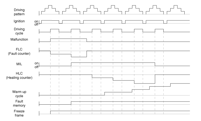
The Relation Between DTC and Driving Pattern in EOBD System
|
1. |
When the same malfunction is detected and maintained during two sequential
driving cycles, the MIL will automatically illuminate.
|
|
2. |
The MIL will go off automatically if no fault is detected after 3 sequential
driving cycles.
|
|
3. |
A Diagnostic Trouble Code (DTC) is recorded in ECM memory when a malfunction
is detected after two sequential driving cycles. The MIL will illuminate
when the malfunction is detected on the second driving cycle.
If a misfire is detected, a DTC will be recorded, and the MIL will illuminate,
immediately after a fault is first detected.
|
|
4. |
A Diagnostic Trouble Code (DTC) will automatically erase from ECM memory
if the same malfunction is not detected for 40 driving cycles.
|
• |
A "warm-up cycle" means sufficient vehicle operation
such that the coolant temperature has risen by at least
40 degrees Fahrenheit from engine starting and reaches
a minimum temperature of 160 degress Fahrenheit.
|
|
• |
A "driving cycle" consists of engine startup, vehicle
operation beyond the beginning of closed loop operation.
|
|
|
Components and components location

1. ECM (Engine
Control Module)
2. Manifold Absolute Pressure Sensor (MAPS)
3. Intake Air Temperature Sensor (IATS)
4. Engine Coolant Temperature Sensor (ECTS)
5. Throttle Position Sensor (TPS)
6. Crankshaft Position Sensor (CKPS)
7. Camshaft Position Sensor (CMPS) [Bank 1 / Intake]
8. Camshaft Position Sensor (CMPS) [Bank 1 / Exhaust]
9. Knock Sensor (KS)
10. Heated Oxygen Sensor (HO2S) [Bank 1 / Sensor 1]
11. Heated Oxygen Sensor (HO2S) [Bank 1 / Sensor 2]
12. Accelerator Position Sensor (APS)
13. A/C Pressure Transducer (APT)
|
14. ETC Motor
15. Injector
16. Purge Control Solenoid Valve (PCSV)
17. Variable Force Solenoid (VFS) [Bank 1 / Intake]
18. Variable Force Solenoid (VFS) [Bank 1 / Exhaust]
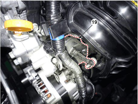
19. Variable Intake Solenoid (VIS)
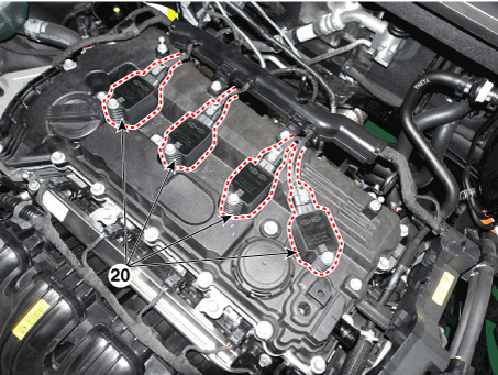
20. Ignition Coil
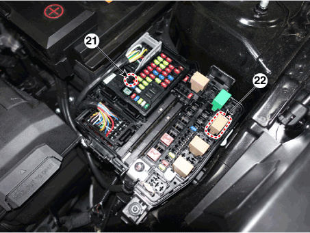
21. Main Relay
22. Fuel Pump Relay
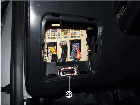
23. Data Link Connector (DLC) [16-Pin]
24. Multi-Purpose Check Connector [16 Pin]
|
1. ECM (Engine Control Module)
|
2. Manifold Absolute Pressure Sensor (MAPS)
3. Intake Air Temperature Sensor (IATS)
|
|
|

|
4. Engine Coolant Temperature Sensor (ECTS)
|
5. Throttle Position Sensor (TPS) [integrated into ETC Module]
14. ETC Motor [integrated into ETC Module]
|
|

|
|
6. Crankshaft Position Sensor (CKPS)
|
7. Camshaft Position Sensor (CMPS) [Bank 1 / Intake]
|
|
|
|
8. Camshaft Position Sensor (CMPS) [Bank 1 / Exhaust]
|
9. Knock Sensor (KS)
|
|
|
|
10. Heated Oxygen Sensor (HO2S) [Bank 1 / Sensor 1]
|
11. Heated Oxygen Sensor (HO2S) [Bank 1 / Sensor 2]
|
|
|
|
12. Accelerator Position Sensor (APS)
|
13. A/C Pressure Transducer (APT)
|
|

|
|
15. Injector
|
16. Purge Control Solenoid Valve (PCSV)
|
|
|

|
17. Variable Force Solenoid (VFS) [Bank 1 / Intake]
|
18. Variable Force Solenoid (VFS) [Bank 1 / Exhaust]
|
|
|

|
19. Variable Intake Solenoid (VIS)
|
20. Ignition Coil
|
|
|
|
21. Main Relay
22. Fuel Pump Relay
|
23. Data Link Connector (DLC) [16-Pin]
|
|
|
|
24. Multi-Purpose Check Connector [16 Pin]
|
|
|

|
|
Engine Control Module (ECM). Schematic diagrams
| ECM Terminal and Input/Output
signal |

Connector A
Pin No
|
Description
|
Connected to
|
1
|
Power ground
|
Chassis Ground
|
2
|
-
|
-
|
3
|
-
|
-
|
4
|
-
|
-
|
5
|
-
|
-
|
6
|
Fuel Sender Signal
|
Fuel Sender
|
7
|
-
|
-
|
8
|
-
|
-
|
9
|
-
|
-
|
10
|
-
|
-
|
11
|
-
|
-
|
12
|
-
|
-
|
13
|
-
|
-
|
14
|
-
|
-
|
15
|
Stop Lamp Signal
|
Stop Lamp
|
16
|
Brake Test Switch
|
Brake Switch
|
17
|
|
|
18
|
-
|
|
19
|
-
|
|
20
|
Output Speed (Supply)
|
ATM Solenoid Valve (Otput Speed)
|
21
|
Input Speed (Supply)
|
ATM Solenoid Valve (Input Speed)
|
22
|
-
|
-
|
23
|
-
|
-
|
24
|
-
|
-
|
25
|
-
|
-
|
26
|
-
|
-
|
27
|
[A/T] SOL. (PWR1)
|
ATM Solenoid Valve
|
28
|
-
|
-
|
29
|
-
|
-
|
30
|
-
|
-
|
31
|
-
|
-
|
-
|
-
|
32
|
-
|
-
|
33
|
-
|
-
|
34
|
-
|
-
|
35
|
-
|
-
|
36
|
-
|
-
|
37
|
-
|
-
|
38
|
APT (Signal)
|
A/C Pressure Transducer (APT)
|
39
|
-
|
-
|
40
|
-
|
-
|
41
|
-
|
-
|
42
|
-
|
-
|
43
|
[A/T] Output Speed (Signal)
|
Engine Control Relay
|
44
|
[A/T] Input Speed (Signal)
|
ATM Solenoid Valve
|
45
|
-
|
-
|
46
|
-
|
-
|
47
|
-
|
-
|
48
|
[A/T] SOL. (VFS_26B)
|
ATM Solenoid Valve
|
49
|
[A/T] SOL. (VFS_OD)
|
ATM Solenoid Valve
|
50
|
[A/T] SOL. (VFS_PWR2)
|
ATM Solenoid Valve
|
51
|
-
|
-
|
52
|
-
|
-
|
53
|
-
|
-
|
54
|
-
|
-
|
55
|
-
|
-
|
56
|
APS (APS. 2 Ground)
|
Accelerator Position Sensor (APS)
|
57
|
APS (APS. 1 Ground)
|
Accelerator Position Sensor (APS)
|
58
|
-
|
-
|
59
|
-
|
-
|
60
|
-
|
-
|
61
|
APT (Ground)
|
A/C Pressure Transducer (APT)
|
62
|
-
|
-
|
63
|
-
|
-
|
64
|
-
|
-
|
65
|
-
|
-
|
66
|
-
|
-
|
67
|
-
|
-
|
68
|
-
|
-
|
69
|
[A/T] SOL. (OTS (-))
|
ATM Solenoid Valve
|
70
|
[A/T] SOL. (OTS (+))
|
ATM Solenoid Valve
|
71
|
-
|
-
|
72
|
[A/T] SOL. (VFS_LINE)
|
ATM Solenoid Valve
|
73
|
[A/T] SOL. (VFS_UD)
|
ATM Solenoid Valve
|
74
|
Start Relay Control
|
B/Alarm Relay
|
75
|
-
|
-
|
76
|
Vehicle Speed Signal
|
IBU & ESP Control Module
|
77
|
-
|
-
|
78
|
-
|
-
|
79
|
APS (APS. 2 Ground)
|
Accelerator Position Sensor (APS)
|
80
|
APS (APS. 1 Ground)
|
Accelerator Position Sensor (APS)
|
81
|
-
|
-
|
82
|
O2 Sensor (Up) (V_N)
|
Oxygen Sensor (Up)
|
83
|
O2 Sensor (Down) (Ground)
|
Oxygen Sensor (Down)
|
84
|
O2 Sensor (Up) (V_RC)
|
Oxygen Sensor (Up)
|
85
|
-
|
-
|
86
|
-
|
-
|
87
|
-
|
-
|
88
|
-
|
-
|
89
|
-
|
-
|
90
|
-
|
-
|
91
|
-
|
-
|
92
|
-
|
-
|
93
|
-
|
-
|
94
|
[A/T] SOL. Power (SS-B)
|
ATM Solenoid Valve
|
95
|
[A/T] SOL. (VFS_35R)
|
ATM Solenoid Valve
|
96
|
Memory Power
|
PCB Block
|
97
|
Wiper 'P' Input
|
PCB Block
|
98
|
-
|
-
|
99
|
-
|
-
|
100
|
-
|
-
|
101
|
-
|
-
|
102
|
APS (APS. 2 Supply)
|
Accelerator Position Sensor (APS)
|
103
|
APS (APS. 1 Supply)
|
Accelerator Position Sensor (APS)
|
104
|
APT (Supply)
|
A/C Pressure Transducer (APT)
|
105
|
O2 Sensor (Up) (V_G)
|
Oxygen Sensor (Up)
|
106
|
O2 Sensor (Down) (Signal)
|
Oxygen Sensor (Down)
|
107
|
O2 Sensor (Up) (V_IP)
|
Oxygen Sensor (Up)
|
108
|
-
|
-
|
109
|
Knock Sensor (Ground)
|
Knock Sensor (KS)
|
110
|
Knock Sensor (Signal)
|
Knock Sensor (KS)
|
111
|
-
|
-
|
112
|
-
|
-
|
113
|
-
|
-
|
114
|
-
|
-
|
115
|
-
|
-
|
116
|
-
|
-
|
117
|
[A/T] SOL. (SS-A)
|
ATM Solenoid Valve
|
118
|
[A/T] SOL. (VFS_T/CON)
|
ATM Solenoid Valve
|
119
|
Memory Power
|
PCB Block
|
Connector B
Pin No
|
Description
|
Connected to
|
1
|
Engine Control Relay 'ON' Input
|
Engine Control Relay
|
2
|
Engine Control Relay 'ON' Input
|
Engine Control Relay
|
3
|
Ground
|
Ground
|
4
|
Ground
|
Ground
|
5
|
Engine Control Relay 'ON' Input
|
PCB Block
|
6
|
P-CAN (High)
|
P-CAN (High)
|
7
|
P-CAN (Low)
|
P-CAN (Low)
|
8
|
-
|
-
|
9
|
-
|
-
|
10
|
-
|
-
|
11
|
-
|
-
|
12
|
-
|
-
|
13
|
OPTS (Signal)
|
Oil Pressure Switch
|
14
|
CMP (IN) (Signal)
|
Camshaft Position Sensor (Intake)
|
15
|
CMP (EX) (Signal)
|
Camshaft Position Sensor (Exhaust)
|
16
|
ETC Motor & Throttle Position Sensor.1 Signal
|
ETC Motor & Throttle Position Sensor
|
17
|
ETC Motor & Throttle Position Sensor Supply
|
ETC Motor & Throttle Position Sensor
|
18
|
-
|
-
|
19
|
-
|
-
|
20
|
-
|
-
|
21
|
-
|
-
|
22
|
-
|
-
|
23
|
-
|
-
|
24
|
Ignition Coil #1 (Control)
|
Ignition Coil #1
|
25
|
O2 Sensor (Up) (Heater)
|
Oxygen Sensor (Up)
|
26
|
O2 Sensor (Down) (Heater)
|
Oxygen Sensor (Down)
|
27
|
-
|
-
|
28
|
-
|
-
|
29
|
Local-CAN (High)
|
Electronic ATM Shift Lever, SCU (High)
|
30
|
Local-CAN (Low)
|
Electronic ATM Shift Lever, SCU (Low)
|
31
|
-
|
-
|
32
|
-
|
-
|
33
|
-
|
-
|
34
|
WTS #1 (Signal)
|
Engine Coolant Temperature Sensor
|
35
|
Sensor Power : Map, CMP (In), CKP
|
Sensor Power : Map, CMP (In), CKP
|
36
|
-
|
-
|
37
|
CMP (In) (Ground)
|
Camshaft Position Sensor (Intake)
|
38
|
CMP (EX) (Ground)
|
Camshaft Position Sensor (Exhaust)
|
39
|
ETC Motor & Throttle Position Sensor.2 Signal
|
ETC Motor & Throttle Position Sensor
|
40
|
-
|
-
|
41
|
-
|
-
|
42
|
Fuel Pump Relay Control
|
Fuel Pump Relay
|
43
|
Engine Control Relay Control
|
Engine Control Relay
|
44
|
-
|
-
|
45
|
-
|
-
|
46
|
A/C Relay Control
|
A/C Relay
|
47
|
Ignition Coil #3 (Control)
|
Ignition Coil #3
|
48
|
ETC DC Motor (+)
|
ETC Motor
|
49
|
ETC DC Motor (-)
|
ETC Motor
|
50
|
-
|
-
|
51
|
ON/Start (Input)
|
ON/Start (Input)
|
52
|
-
|
-
|
53
|
-
|
-
|
54
|
-
|
-
|
55
|
-
|
-
|
56
|
-
|
-
|
57
|
WTS #1 (Ground)
|
Engine Coolant Temperature Sensor
|
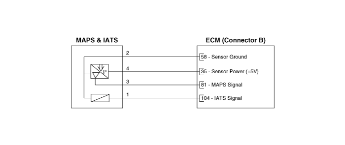
58
|
MAP & IAT Ground
|
MAP Sensor
|
59
|
-
|
-
|
60
|
-
|
-
|
61
|
-
|
-
|
62
|
ETC (TPS Groud)
|
ETC Motor & Throttle Position Sensor
|
63
|
-
|
-
|
64
|
-
|
-
|
65
|
Start Relay (Low Side)
|
Start Relay
|
66
|
-
|
-
|
67
|
-
|
-
|
68
|
-
|
-
|
69
|
-
|
-
|
70
|
OCV Control (EX)
|
CVVT Oil Control Valve (OCV)
|
71
|
OCV Control (IN)
|
CVVT Oil Control Valve (OCV)
|
72
|
-
|
-
|
73
|
-
|
-
|
74
|
-
|
-
|
75
|
Local-CAN2 (High)
|
Can Check
|
76
|
Local-CAN2 (Low)
|
Can Check
|
77
|
Alternator (IN)
|
Alternator
|
78
|
-
|
-
|
79
|
-
|
-
|
80
|
CKP (Ground)
|
Crankshaft Position Sensor (CKPS)
|
81
|
MAP Sensor (Signal)
|
MAP Sensor
|
82
|
Ignition Coil #1/#4 (Feedback)
|
Ignition Coil #1 / #4 (Feedback)
|
83
|
-
|
-
|
84
|
-
|
-
|
85
|
-
|
-
|
86
|
-
|
-
|
87
|
-
|
-
|
88
|
C/FAN Motor (PWM Signal)
|
C/FAN Motor
|
89
|
PCSV Control
|
Purge Control Solanoid Valve
|
90
|
CCV Control (Not Used)
|
Canister Close Valve
|
91
|
-
|
-
|
92
|
VIS Control
|
Variable Intake Solenoid Valve (VIS)
|
93
|
Ignition Coil #4 Control
|
Ignition Coil #4
|
94
|
Injector Coil #4 Control
|
Injector Coil #4
|
95
|
-
|
-
|
96
|
-
|
-
|
97
|
-
|
-
|
98
|
-
|
-
|
99
|
IMMO. Data Line
|
Immobilizer
|
100
|
-
|
-
|
101
|
-
|
-
|
102
|
-
|
-
|
103
|
Crankshaft Position Sensor (CKPS) signal input
|
Crankshaft Position Sensor (CKPS)
|
104
|
IAT Sensor
|
MAP Sensor
|
105
|
Ignition Coil #2 / #3 (Feedback)
|
Ignition Coil #2 / #3 (Feedback)
|
106
|
-
|
-
|
107
|
-
|
-
|
108
|
CMP (EX) (Supply)
|
Camshaft Position Sensor (CMPS)
|
109
|
FTPS (Not Used)
|
Fuel Tank Pressure Sensor (FTPS)
|
110
|
Engine RPM Signal
|
Engine RPM Signal
|
111
|
-
|
-
|
112
|
-
|
-
|
113
|
-
|
-
|
114
|
-
|
-
|
115
|
Thermostat PWM
|
Electronic Thermostat
|
116
|
Ignition Coil #2 Control
|
Ignition Coil #2
|
117
|
Injector Coil #1 Control
|
Injector Coil #1
|
118
|
Injector Coil #3 Control
|
Injector Coil #3
|
119
|
Injector Coil #2 Control
|
Injector Coil #2
|
Engine Control Module (ECM). Repair procedures
| •
|
If you replace the PCM, you must perform oil pressure characteristics
back up & input (TCU Replacement).
(Refer to Automatic Transaxle System - "Automatic Transaxle
Control System")
|
|
| •
|
When replacing the ECM, the vehicle equipped with the immobilizer
must be performed procedure as below.
|
[In the case of installing used ECM]
| 1) |
Perform "ECM Neutral mode" procedure with diagnostic tool.
(Refer to Body Electric System - "Immobilizer System")
|
| 2) |
After finishing "ECM Neutral mode", perform "Key teaching" procedure
with diagnostic tool.
(Refer to Body Electric System - "Immobilizer System")
|
[In the case of installing new ECM]
| –
|
Perform "Key teaching" procedure with diagnostic tool.
(Refer to Body Electric System - "Immobilizer System")
|
|
| •
|
When replacing the ECM, the vehicle equipped with the smart
key system (Button start) must be performed procedure as below.
|
[In the case of installing used ECM]
| 1) |
Perform "ECM Neutral mode" procedure with diagnostic tool.
(Refer to Body Electric System - "Smart Key")
|
| 2) |
After finishing "ECM Neutral mode", insert the key (or press
the start button) and turn it to the IGN ON and OFF position.
Then the ECM learns the smart key information automatically.
|
[In the case of installing new ECM]
| –
|
Insert the key (or press the start button) and turn it to the
IGN ON and OFF position. Then the ECM learns the smart key information
automatically.
|
|
|
1. |
Turn the ignition switch OFF and disconnect the battery negative (-)
terminal.
|
|
2. |
Remove the air cleaner assembly.
(Refer to Engine Mechanical System - "Air Cleaner")
|
|
3. |
Disconnect the ECM connector (A).

|
|
4. |
Remove the mounting bolt (A) and nuts (B), and then remove the ECM (C).
|
| •
|
When replacing the ECM, the vehicle equipped with the immobilizer
must be performed procedure as below.
|
[In the case of installing used ECM]
| 1) |
Perform "ECM Neutral mode" procedure with diagnostic tool.
(Refer to Body Electric System - "Immobilizer System")
|
| 2) |
After finishing "ECM Neutral mode", perform "Key teaching" procedure
with diagnostic tool.
(Refer to Body Electric System - "Immobilizer System")
|
[In the case of installing new ECM]
| –
|
Perform "Key teaching" procedure with diagnostic tool.
(Refer to Body Electric System - "Immobilizer System")
|
|
| •
|
When replacing the ECM, the vehicle equipped with the smart
key system (Button start) must be performed procedure as below.
|
[In the case of installing used ECM]
| 1) |
Perform "ECM Neutral mode" procedure with diagnostic tool.
(Refer to Body Electric System - "Smart Key")
|
| 2) |
After finishing "ECM Neutral mode", insert the key (or press
the start button) and turn it to the IGN ON and OFF position.
Then the ECM learns the smart key information automatically.
|
[In the case of installing new ECM]
| –
|
Insert the key (or press the start button) and turn it to the
IGN ON and OFF position. Then the ECM learns the smart key information
automatically.
|
|
|
1. |
Install in the reverse order of removal.
|
| ECM Problem Inspection Procedure |
|
1. |
TEST ECM GROUND CIRCUIT : Measure resistance between ECM and chassis
ground using the backside of ECM harness connector as ECM side check
point. If the problem is found, repair it.
|
|
2. |
TEST ECM CONNECTOR : Disconnect the ECM connector and visually check
the ground terminals on ECM side and harness side for bent pins or poor
contact pressure. If the problem is found, repair it.
|
|
3. |
If problem is not found in Step 1 and 2, the ECM could be faulty. If
so, make sure there were no DTC's before swapping the ECM with a new
one, and then check the vehicle again. If DTC's were found, examine
this first before swapping ECM.
|
|
4. |
RE-TEST THE ORIGINAL ECM : Install the original ECM (may be broken)
into a known-good vehicle and check the vehicle. If the problem occurs
again, replace the original ECM with a new one. If problem does not
occur, this is intermittent problem.
(Refer to "Intermittent Problem Inspection Procedure" in Basic Inspection
Procedure)
|
VIN Programming Procedure
VIN (Vehicle Identification Number) is a number that has the vehicle's information
(Maker, Vehicle Type, Vehicle Line/Series, Body Type, Engine Type, Transmission
Type, Model Year, Plant Location and so forth. For more information, please
refer to the group "GI" in this SERVICE MANUAL). When replacing an ECM, the
VIN must be programmed in the ECM. If there is no VIN in ECM memory, the fault
code (DTC P0630) is set.
| •
|
The programmed VIN cannot be changed. When writing the VIN,
confirm the VIN carefully
|
|
|
1. |
Turn OFF the ignition switch.
|
|
2. |
Connect the diagnostic tool to Data Link Connector (DLC).
|
|
3. |
Turn ON the ignition switch.
|
|
4. |
Select "Vehicle, Model Year, Engine, System".
|
|
5. |
Select "Vehicle S/W Management".
|
|
6. |
Select "Write VIN".

|
|
7. |
Input the VIN.
|
• |
Before inputing the VIN, confirm the VIN again because
the programmed VIN cannot be changed.
|
|

|
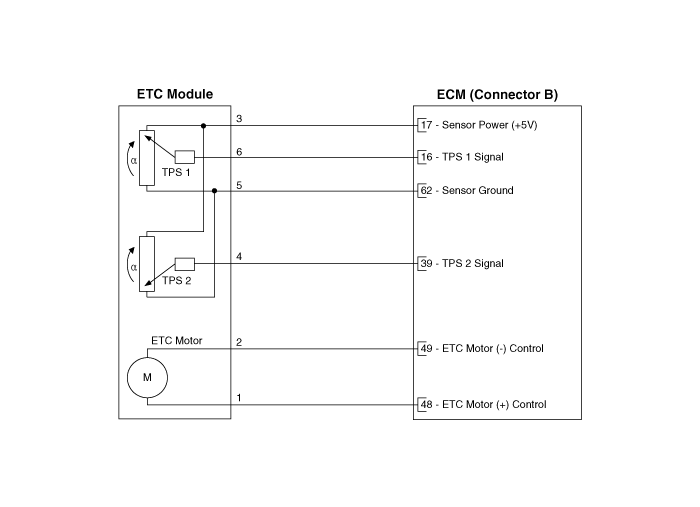
ETC (Electronic Throttle Control) System
Description and operation
The Electronic Throttle Control (ETC) System consists of a throttle body with
an integrated control motor and throttle position sensor (TPS). Instead of the
traditional throttle cable, an Accelerator Position Sensor (APS) is used to
receive driver input. The ECM uses the APS signal to calculate the target throttle
angle; the position of the throttle is then adjusted via ECM control of the
ETC motor. The TPS signal is used to provide feedback regarding throttle position
to the ECM. Using ETC, precise control over throttle position is possible; the
need for external cruise control modules/cables is eliminated.

Troubleshooting
Item
|
Fail-Safe
|
ETC Motor
|
Throttle valve stuck at 5°
|
TPS
|
TPS 1 fault
|
Replace it with TPS2
|
TPS 2 fault
|
Replace it with TPS1
|
TPS 1, 2 fault
|
Throttle valve stuck at 5°
|
APS
|
TPS 1 fault
|
Replace it with TPS2
|
TPS 2 fault
|
Replace it with TPS1
|
TPS 1, 2 fault
|
Throttle valve stuck at 5°
|
| •
|
When throttle value is stuck at 5°, engine speed is limited
at below 1,500rpm and vehicle speed at maximum 40 - 50 km/h
(25 - 31 mph).
|
|
Specifications
[Throttle Position Sensor (TPS)]
Throttle Angle (°)
|
Output Voltage (V)
|
TPS1
|
TPS2
|
0
|
0.0
|
5.0
|
10
|
0.48
|
4.52
|
20
|
0.95
|
4.05
|
30
|
1.43
|
3.57
|
40
|
1.90
|
3.10
|
50
|
2.38
|
2.62
|
60
|
2.86
|
2.14
|
70
|
3.33
|
1.67
|
80
|
3.81
|
1.19
|
90
|
4.29
|
0.71
|
100
|
4.76
|
0.24
|
105
|
5.0
|
0
|
C.T (6 - 15°)
|
0.29 - 0.71
|
4.29 - 4.71
|
W.O.T (93 - 102°)
|
4.43 - 4.86
|
0.14 - 0.57
|

Item
|
Sensor Resistance (kΩ)
|
TPS1
|
0.875 - 1.625 [20°C (68°F)]
|
TPS2
|
0.875 - 1.625 [20°C (68°F)]
|
[ETC Motor]
Item
|
Specification
|
Coil Resistance (Ω)
|
1.2 - 1.8 [20°C (68°F)]
|
Schematic diagrams
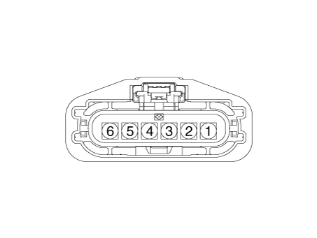
Harness Connector
Repair procedures
Throttle Position Sensor (TPS)
|
1. |
Connect the diagnostic tool on the Data Link Connector (DLC).
|
|
2. |
Start the engine and measure the output voltage of TPS 1 and 2 at C.T.
and W.O.T.
Throttle Angle
|
Output Voltage (V)
|
TPS 1
|
TPS 2
|
C.T
|
0.3 - 0.9
|
4.2 - 5.0
|
W.O.T
|
1.5 - 3.0
|
3.3 - 3.8
|
|
|
3. |
Turn the ignition switch OFF and disconnect the scantool from the DLC.
|
|
4. |
Disconnect the ETC module connector and measure the resistance between
the ETC module terminals 1 and 2.
|
Specification : Refer to "Specification"
|
|
ETC Motor
|
1. |
Turn the ignition switch OFF.
|
|
2. |
Disconnect the ETC module connector.
|
|
3. |
Measure resistance between the ETC module terminals 3 and 6.
|
|
4. |
Check that the resistance is within the specification.
|
Specification : Refer to "Specification"
|
|
|
1. |
Turn the ignition switch OFF and disconnect the battery negative (-)
cable.
|
|
2. |
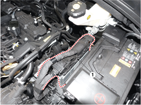
Remove the resonator and the air intake hose.
(Refer to Engine Mechanical System - "Intake Manifold")
|
|
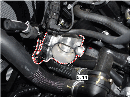
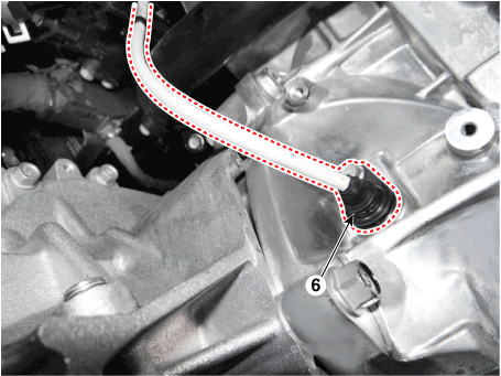
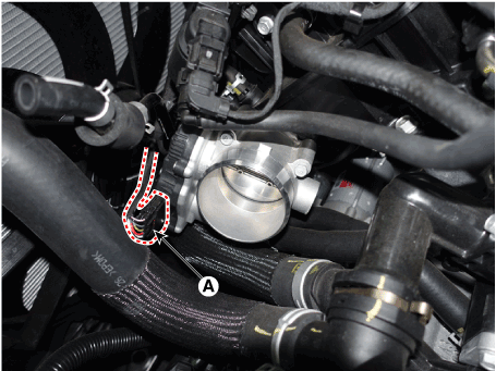
3. |
Disconnect the ETC module connector (A).
|
|
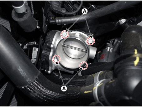
4. |
Remove the installation bolts (A), and then remove the ETC module from
the engine.
|
Tightening Torque :
7.8 - 11.8 N.m (0.8 - 1.2 kgf.m, 5.8 - 8.7 lb-ft)
|
|
| •
|
Install the component with the specified torques.
|
| •
|
Note that internal damage may occur when the component is dropped.
In this case, use it after inspecting.
|
|
|
1. |
Installation is reverse of removal.
|
Manifold Absolute Pressure Sensor (MAPS). Description and operation
Manifold Absolute Pressure Sensor (MAPS) is a speed-density type sensor and
is installed on the surge tank. It senses absolute pressure of the surge tank
and transfers the analog signal proportional to the pressure to the ECM. By
using this signal, the ECM calculates the intake air quantity and engine speed.
The MAPS consists of a piezo-electric element and a hybrid IC amplifying the
element output signal. The element is silicon diaphragm type and adapts pressure
sensitive variable resistor effect of semi-conductor. Because 100% vacuum and
the manifold pressure apply to both sides of the sensor respectively, this sensor
can output analog signal by using the silicon variation proportional to pressure
change.

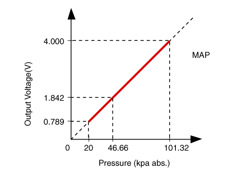
Manifold Absolute Pressure Sensor (MAPS). Specifications
Pressure (kPa)
|
Output Voltage (V)
|
20.0
|
0.79
|
46.7
|
1.84
|
101.3
|
4.0
|
Manifold Absolute Pressure Sensor (MAPS). Schematic diagrams
Harness Connector
Manifold Absolute Pressure Sensor (MAPS). Repair procedures
|
1. |
Connect the diagnostic tool on the Data Link Connector (DLC).
|
|
2. |
Measure the output voltage of the MAPS at idle and IG ON.
|
Specification : Refer to "Specification"
|
|
|
1. |
Turn the ignition switch OFF and disconnect the battery negative (-)
cable.
|
|
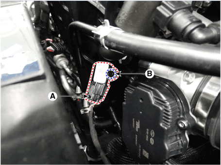
2. |
Disconnect the manifold absolute pressure sensor connector (A).
|
|
3. |
Remove the installation bolt (B), and then remove the sensor from the
surge tank.
|
Tightening Torque :
9.8 - 11.8 N.m (1.0 - 1.2 kgf.m, 7.2 - 8.7 lb-ft)
|
|
| •
|
Install the component with the specified torques.
|
| •
|
Note that internal damage may occur when the component is dropped.
In this case, use it after inspecting.
|
|
| •
|
Insert the sensor in the installation hole and be careful not
to damage when installation.
|
|
|
1. |
Installation is reverse of removal.
|
Intake Air Temperature Sensor (IATS). Description and operation
Intake Air Temperature Sensor (IATS) is included inside Manifold Absolute Pressure
Sensor and detects the intake air temperature.
To calculate precise air quantity, correction of the air temperature is needed
because air density varies according to the temperature. So the ECM uses not
only MAPS signal but also IATS signal. This sensor has a Negative Temperature
Coefficient (NTC) Thermister and it's resistance changes in reverse proportion
to the temperature.
Intake Air Temperature Sensor (IATS). Specifications
Temperature [°C (°F)]
|
Resistance (kΩ)
|
-40 (-40)
|
40.93 - 48.35
|
-20 (-4)
|
13.89 - 16.03
|
0 (32)
|
5.38 - 6.09
|
10 (50)
|
3.48 - 3.90
|
20 (68)
|
2.31 - 2.57
|
40 (104)
|
1.08 - 1.21
|
60 (140)
|
0.54 - 0.62
|
80 (176)
|
0.29 - 0.34
|
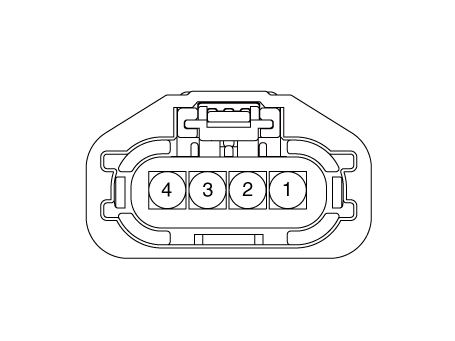
Intake Air Temperature Sensor (IATS). Schematic diagrams
Harness Connector
Intake Air Temperature Sensor (IATS). Repair procedures
|
1. |
Turn the ignition switch OFF.
|
|
2. |
Disconnect the IATS connector.
|
|
3. |
Measure resistance between the IATS terminals 3 and 4.
|
|
4. |
Check that the resistance is within the specification.
|
Specification : Refer to "Specification"
|
|
|
1. |
Turn the ignition switch OFF and disconnect the battery negative (-)
cable.
|
|
2. |
Disconnect the manifold absolute pressure sensor connector (A).
|
|
3. |
Remove the installation bolt (B), and then remove the sensor from the
surge tank.
|
Tightening Torque :
9.8 - 11.8 N.m (1.0 - 1.2 kgf.m, 7.2 - 8.7 lb-ft)
|
|
| •
|
Install the component with the specified torques.
|
| •
|
Note that internal damage may occur when the component is dropped.
In this case, use it after inspecting.
|
|
| •
|
Insert the sensor in the installation hole and be careful not
to damage when installation.
|
|
|
1. |
Installation is reverse of removal.
|
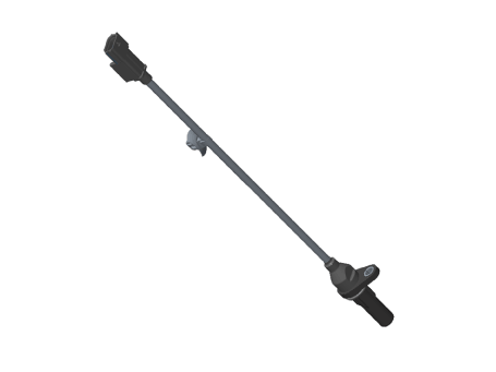
Engine Coolant Temperature Sensor (ECTS). Description and operation
Engine Coolant Temperature Sensor (ECTS) is located in the engine coolant passage
of the cylinder head for detecting the engine coolant temperature. The ECTS
uses a thermistor whose resistance changes with the temperature.
The electrical resistance of the ECTS decreases as the temperature increases,
and increases as the temperature decreases. The reference +5V is supplied to
the ECTS via a resistor in the ECM. That is, the resistor in the ECM and the
thermistor in the ECTS are connected in series. When the resistance value of
the thermistor in the ECTS changes according to the engine coolant temperature,
the output voltage also changes.
During cold engine operation, the ECM increases the fuel injection duration
and controls the ignition timing using the information of engine coolant temperature
to avoid engine stalling and improve drivability.

Engine Coolant Temperature Sensor (ECTS). Specifications
Temperature [°C (°F)]
|
Resistance (kΩ)
|
-40 (-40)
|
41.74 - 54.54
|
-30 (-22)
|
23.54 - 29.94
|
-20 (-4)
|
14.13 - 16.83
|
-10 (14)
|
8.39 - 10.22
|
0 (32)
|
5.28 - 6.29
|
10 (50)
|
3.42 - 4.00
|
20 (68)
|
2.31 - 2.59
|
30 (86)
|
1.55 - 1.76
|
40 (104)
|
1.08 - 1.21
|
50 (122)
|
0.77 - 0.85
|
60 (140)
|
0.56 - 0.61
|
70 (158)
|
0.41 - 0.44
|
80 (176)
|
0.31 - 0.33
|
90 (194)
|
0.23 - 0.25
|
100 (212)
|
0.18 - 0.19
|
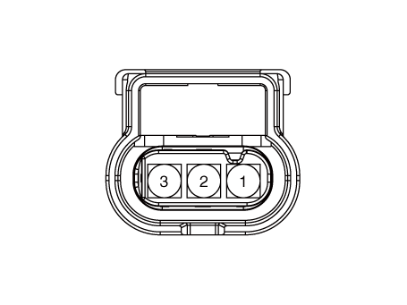
Engine Coolant Temperature Sensor (ECTS). Schematic diagrams
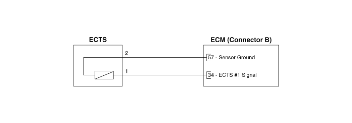
Harness Connector

Engine Coolant Temperature Sensor (ECTS). Repair procedures
|
1. |
Turn the ignition switch OFF.
|
|
2. |
Disconnect the ECTS connector.
|
|
4. |
After immersing the thermistor of the sensor into engine coolant, measure
resistance between the ECTS terminals 3 and 4.
|
|
5. |
Check that the resistance is within the specification.
|
Specification : Refer to "Specification"
|
|
|
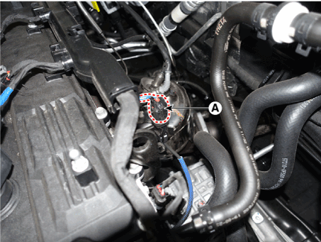
1. |
Turn the ignition switch OFF and disconnect the battery negative (-)
cable.
|
|
2. |
Remove the engine control module.
(Refer to Engine Control/Fuel System - "Engine Control Module (ECM)")
|
|
3. |
Disconnect the engine coolant temperature sensor connector (A).
|
|
4. |
Remove the installation bolts (B), and then remove the engine coolant
temperature sensor from the engine.
|
Tightening Torque :
9.8 - 11.8 N.m (1.0 - 1.2 kgf.m, 7.2 - 8.7 lb-ft)
|

|
• |
Note that engine coolant may be flowed out from the
water temperature control assembly when removing the
sensor.
|
|
|
|
5. |
Supplement the engine coolant.
(Refer to Engine Mechanical System - "Coolant")
|
| •
|
Install the component with the specified torques.
|
| •
|
Note that internal damage may occur when the component is dropped.
In this case, use it after inspecting.
|
|
| •
|
Apply the engine coolant to the O-ring.
|
|
| •
|
Insert the sensor in the installation hole and be careful not
to damage when installation.
|
|
|
1. |
Installation is reverse of removal.
|
Crankshaft Position Sensor (CKPS). Description and operation
Crankshaft Position Sensor (CKPS) detects the crankshaft position and is one
of the most important sensors of the engine control system. If there is no CKPS
signal input, the engine may stop because of CKPS signal missing. This sensor
is installed on the cylinder block or the transaxle housing and generates alternating
current by magnetic flux field which is made by the sensor and the target wheel
when engine runs.
The target wheel consists of 58 slots and 2 missing slots on 360 degrees CA
(Crank Angle).
Crankshaft Position Sensor (CKPS). Schematic diagrams

Harness Connector
Crankshaft Position Sensor (CKPS). Repair procedures
|
1. |
Check the signal waveform of the CMPS and CKPS using the diagnostic
tool.
|
Specification : Refer to "DTC Diagnostic Guide"
|
|
| •
|
Be careful not to damage the parts located under the vehicle
(floor under cover, fuel filter, fuel tank and canister) when
raising the vehicle using the lift.
(Refer to General Information - "Lift and Support Points")
|
|
|
1. |
Turn the ignition switch OFF and disconnect the battery negative (-)
cable.
|
|
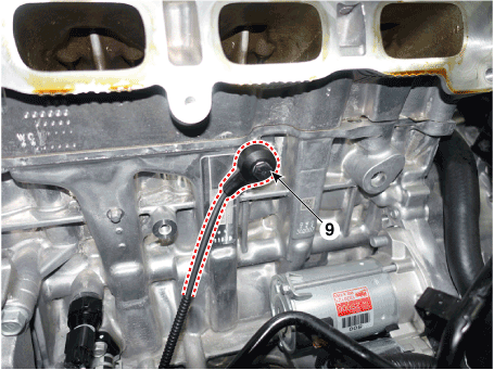
2. |
Disconnect the crankshaft position sensor connector (A).
|
|
4. |
Remove the engine room under cover.
(Refer to Engine Mechanical System - "Engine Room Under Cover")
|
|
5. |
Remove the protector (A).

|
|
6. |
Remove the installation bolt (A), and then remove the crankshaft position
sensor.
|
Tightening Torque :
9.8 - 11.8 N.m (1.0 - 1.2 kgf.m, 7.2 - 8.7 lb-ft)
|

|
| •
|
Install the component with the specified torques.
|
| •
|
Note that internal damage may occur when the component is dropped.
In this case, use it after inspecting.
|
|
| •
|
Apply the engine oil to the O-ring.
|
|
| •
|
Insert the sensor in the installation hole and be careful not
to damage when installation.
|
|
|
1. |
Installation is reverse of removal.
|
Crankshaft position sensor installation bolt : 9.8 - 11.8 N.m
(1.0 - 1.2 kgf.m, 7.2 - 8.7 lb-ft)
Crankshaft position sensor protector installation bolt (M8)
: 18.6 - 23.5 N.m
(1.9 - 2.4 kgf.m, 13.7 - 17.4 lb-ft)
Crankshaft position sensor protector installation bolt (M6)
: 9.8 - 11.8 N.m (1.0 - 1.2 kgf.m, 7.2 - 8.7 lb-ft)
|
|
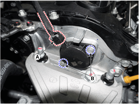
Camshaft Position Sensor (CMPS). Description and operation
Camshaft Position Sensor (CMPS) is a hall sensor and detects the camshaft position
by using a hall element.
It is related with Crankshaft Position Sensor (CKPS) and detects the piston
position of each cylinder which the CKPS can't detect.
The CMPS is installed on engine head cover and uses a target wheel installed
on the camshaft. The Cam Position sensor is a hall-effect type sensor. As the
target wheel passes the Hall sensor, the magnetic field changes in the sensor.
The sensor then switches a signal which creates a square wave.

Camshaft Position Sensor (CMPS). Schematic diagrams

Harness Connector
Camshaft Position Sensor (CMPS). Repair procedures
|
1. |
Check the signal waveform of the CMPS and CKPS using the diagnostic
tool.
|
Specification : Refer to "DTC Diagnostic Guide"
|
|
| •
|
DON’T remove the camshaft position sensor during engine running
or right after engine stops, or a scald by the flowed out engine
oil may occur.
|
|
[Bank 1 / Intake]
|
1. |
Turn the ignition switch OFF and disconnect the battery negative (-)
cable.
|
|
2. |
Disconnect the camshaft position sensor connector (A).
|
|
3. |
Remove the installation bolt, and then remove the sensor (B).
|
Tightening Torque :
9.8 - 11.8 N.m (1.0 - 1.2 kgf.m, 7.2 - 8.7 lb-ft)
|
|
[Bank 1 / Exhaust]
|
1. |
Turn the ignition switch OFF and disconnect the battery negative (-)
cable.
|
|
2. |
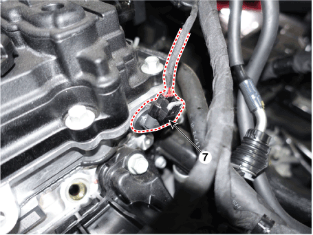
Disconnect the camshaft position sensor connector (A).
|
|
3. |
Remove the hanger and the protector.
|
|
4. |
Remove the installation bolt, and then remove the sensor.
|
Tightening Torque :
9.8 - 11.8 N.m (1.0 - 1.2 kgf.m, 7.2 - 8.7 lb-ft)
|

|
| •
|
Install the component with the specified torques.
|
| •
|
Note that internal damage may occur when the component is dropped.
In this case, use it after inspecting.
|
|
| •
|
Apply the engine oil to the O-ring.
|
|
| •
|
Insert the sensor in the installation hole and be careful not
to damage when installation.
|
|
| •
|
Be careful not to damage the sensor housing and the connector.
|
| •
|
Be careful not to damage the O-ring.
|
|
|
1. |
Installation is reverse of removal.
|
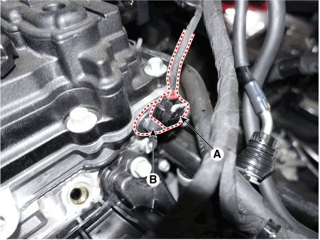
Knock Sensor (KS). Description and operation
Knocking is a phenomenon characterized by undesirable vibration and noise and
can cause engine damage. Knock Sensor (KS) is installed on the cylinder block
and senses engine knocking.
When knocking occurs, the vibration from the cylinder block is applied as pressure
to the piezoelectric element. When a knock occurs, the sensor produces voltage
signal. The ECM retards the ignition timing when knocking occurs. If the knocking
disappears after retarding the ignition timing, the ECM will advance the ignition
timing. This sequential control can improve engine power, torque and fuel economy.

Knock Sensor (KS). Specifications
Item
|
Specification
|
Capacitance (pF)
|
850 - 1,150
|
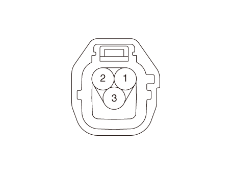
Knock Sensor (KS). Schematic diagrams
Harness Connector
Knock Sensor (KS). Repair procedures
|
1. |
Turn the ignition switch OFF and disconnect the battery negative (-)
cable.
|
|
2. |
Remove the intake manifold.
(Refer to Engine Mechanical System - "Intake Manifold")
|
|
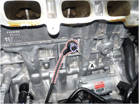
3. |
Remove the installation bolt (A), and then remove the sensor from the
cylinder block.
|
Tightening Torque :
18.6 - 23.5 N.m (1.9 - 2.4 kgf.m, 13.7 - 17.4 lb-ft)
|
|
| •
|
Install the component with the specified torques.
|
| •
|
Note that internal damage may occur when the component is dropped.
In this case, use it after inspecting.
|
|
|
1. |
Installation is reverse of removal.
|
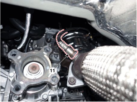
Heated Oxygen Sensor (HO2S). Description and operation
Heated Oxygen Sensor (HO2S) consists of zirconium and alumina and is installed
both upstream and downstream of the Manifold Catalytic Converter. It varies
in accordance with the air/fuel ratio.
The sensor must be hot in order to operate normally. To keep it hot, the sensor
has a heater which is controlled by the ECM via a duty cycle signal. When the
exhaust gas temperature is lower than the specified value, the heater warms
the sensor tip.
Heated Oxygen Sensor (HO2S). Specifications
HO2S [Bank 1 / Sensor 1] [Euro-V]
Item
|
Specification
|
Heater Resistance (Ω)
|
2.5 - 4.0 [20°C (68°F)]
|
HO2S [Bank 1 / Sensor 1] [Except Euro-V]
A/F Ratio (λ)
|
Output Voltage (V)
|
RICH
|
Approx. 0.9
|
LEAN
|
Approx. 0.04
|
Item
|
Specification
|
Heater Resistance (Ω)
|
3.3 - 4.1Ω [21°C (69.8°F)]
|
HO2S [Bank 1 / Sensor 2]
A/F Ratio (λ)
|
Output Voltage (V)
|
RICH
|
Approx. 0.9
|
LEAN
|
Approx. 0.04
|
Item
|
Specification
|
Heater Resistance (Ω)
|
3.3 - 4.1Ω [21°C (69.8°F)]
|
Heated Oxygen Sensor (HO2S). Schematic diagrams

Harness Connector
[Bank 1 / Sensor 1]
[Bank 1 / Sensor 2]

Heated Oxygen Sensor (HO2S). Repair procedures
|
1. |
Turn the ignition switch OFF.
|
|
2. |
Disconnect the HO2S connector.
|
|
3. |
Measure resistance between the HO2S terminals 4 and 5 [B1/S1] [Euro-V].
|
|
4. |
Measure resistance between the HO2S terminals 3 and 4 [B1/S1] [Except
Euro-V].
|
|
5. |
Measure resistance between the HO2S terminals 3 and 4 [B1/S2].
|
|
6. |
Check that the resistance is within the specification.
|
Specification : Refer to "Specification"
|
|
|
1. |
Turn the ignition switch OFF and disconnect the battery negative (-)
cable.
|
|
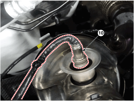
2. |
Disconnect the connector (A), and then remove the sensor (B).
|
Tightening Torque :
39.2 - 49.1 N.m (4.0 - 5.0 kgf.m, 28.9 - 36.2 lb-ft)
|
|
• |
Note that the SST (Part No. : 09392-2H100) is useful
when removing the heated oxygen sensor.
|
|
[Bank 1 / Sensor 1]

[Bank 1 / Sensor 2]
|
| •
|
Install the component with the specified torques.
|
| •
|
Note that internal damage may occur when the component is dropped.
In this case, use it after inspecting.
|
|
| •
|
DON’T use a cleaner, spray, or grease to sensing element and
connector of the sensor because oil component in them may malfunction
the sensor performance.
|
| •
|
Sensor and its wiring may be damaged in case of contacting with
the exhaust system (Exhaust Manifold, Catalytic Converter, and
so on).
|
|
|
1. |
Installation is reverse of removal.
|
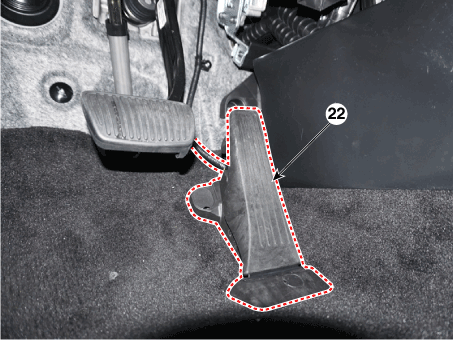
Accelerator Position Sensor (APS). Description and operation
On electronic injection systems, there is no longer a load lever that mechanically
controls the fuelling. The flow is caculated by the ECM depending on a number
of parameters, including pedal position, which is measured using a potentiometer.
The pedal sensor has two potentio-meters whoses slides are mechanically solid.
The two potentiometers are supplied from distinct and different power sources
so there is built in redundancy of information giving reliable driver's request
information. A voltage is generated across the potentiometer in the acceleration
position sensor as a function of the accelerator-pedal setting. Using a peogrammed
characteristic curve, the pedal's position is then calculated from this voltage.
Accelerator Position Sensor (APS). Specifications
Accelerator Position
|
Output Voltage (V) [Vref=5V]
|
APS 1
|
APS 2
|
C.T
|
0.7 - 0.8
|
0.33 - 0.43
|
W.O.T
|
3.98 - 4.35
|
1.93 - 2.17
|

Accelerator Position Sensor (APS). Schematic diagrams
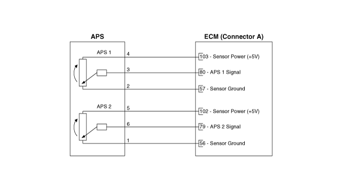
Harness Connector

Accelerator Position Sensor (APS). Repair procedures
|
1. |
Connect the diagnostic tool on the Data Link Connector (DLC).
|
|
2. |
Turn the ignition switch ON.
|
|
3. |
Measure the output voltage of the APS 1 and 2 at C.T and W.O.T.
Accelerator Position
|
Output Voltage (V) [Vref=5V]
|
APS 1
|
APS 2
|
C.T
|
0.7 - 0.8
|
0.33 - 0.43
|
W.O.T
|
3.98 - 4.35
|
1.93 - 2.18
|
|
|
1. |
Turn the ignition switch OFF and disconnect the battery (-) terminal.
|
|
2. |
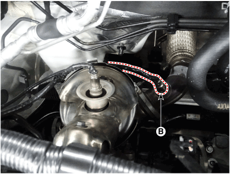
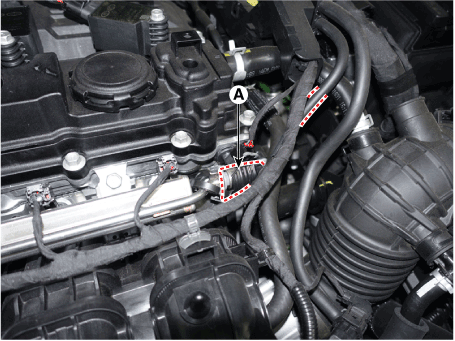
Disconnect the accelerator position snesor connector (A).

|
|
3. |
Disconnect the mounting cap (A).

|
|
4. |
Remove the accelerator pedal module from the vehicle after loosening
the mounting bolt (A).
|
Tightening Torque :
8.8 - 13.7 N.m (0.9 - 1.4 kgf.m, 6.5 - 10.1 lb.ft)
|

|
|
1. |
Install in the reverse order of removal.
|
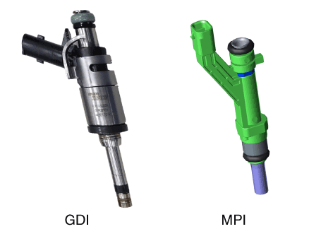
Injector. Description and operation
Based on information from various sensors, the ECM can calculate the fuel amount
to be injected. The fuel injector is a solenoid-operated valve and the fuel
injection amount is controlled by length of injection time. The ECM controls
each injector by grounding the control circuit. When the ECM energizes the injector
by grounding the control circuit, the circuit voltage should be low (theoretically
0V) and the fuel is injected. When the ECM de-energizes the injector by opening
control circuit, the fuel injector is closed and circuit voltage should momentarily
peak.
Injector. Specifications
Item
|
Specification
|
Coil Resistance (Ω)
|
13.8 - 15.2 [20°C (68°F)]
|
Injector. Schematic diagrams

Harness Connector

Injector. Repair procedures
|
1. |
Turn the ignition switch OFF.
|
|
2. |
Disconnect the injector connector.
|
|
3. |
Measure resistance between the injector terminals 1 and 2.
|
|
4. |
Check that the resistance is within the specification.
|
Specification : Refer to "Specification"
|
|
|
1. |
Release the residual pressure in fuel line.
Release the residual pressure in fuel line.
|
|
2. |
Turn the ignition switch OFF and disconnect the battery (-) terminal.
|
|
3. |
Disconnect the fuel delivery line quick-connector (A).
|
• |
Open the clamp cover (B) before disconnecting the quick-connector.
(If the clip is applied)
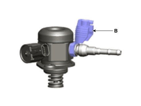
|
|
|
• |
When removing the quick-connnector with the clip removing
tool (A), be careful not to damage the plastic clip
(B).
|
|
• |
If the clip is damaged, it can cause a fuel leak due
to bad connection and could result in a fire.
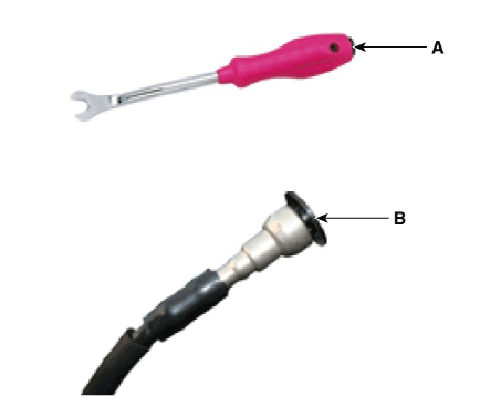
|
|
|
|
4. |
Disconnect the injector connector (A).

|
|
5. |
Remove the delivery pipe & injector assembly after loosening the bolt
(A).
|
Tightening Torque
18.6 - 23.5 N.m (1.9 - 2.4 kgf.m, 13.7 - 17.4 lb-ft)
|

|
|
6. |
Remove the injector from the delivery pipe (A) after releasing the fixing
clip both side as shown below.
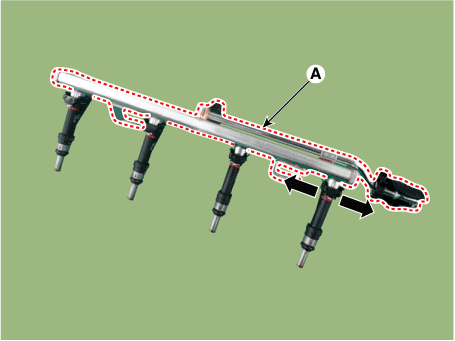
|
| •
|
Install the component with the specified torques.
|
| •
|
Note that internal damage may occur when the component is dropped.
In this case, use it after inspecting.
|
|
| •
|
Apply the engine oil to the injector O-ring.
|
|
| •
|
Inspect the injector O-ring when installing.
|
|
|
1. |
Installation is reverse of removal.
|
Purge Control Solenoid Valve (PCSV). Description and operation
Purge Control Solenoid Valve (PCSV) is installed on the surge tank and controls
the passage between the canister and the intake manifold. It is a solenoid valve
and is open when the ECM grounds the valve control line. When the passage is
open (PCSV ON), fuel vapor stored in the canister is transferred to the intake
manifold.

Purge Control Solenoid Valve (PCSV). Specifications
Item
|
Specification
|
Coil Resistance (Ω)
|
19.0 - 22.0 [20°C (68°F)]
|
Purge Control Solenoid Valve (PCSV). Schematic diagrams

Harness Connector

Purge Control Solenoid Valve (PCSV). Repair procedures
|
1. |
Turn the ignition switch OFF.
|
|
2. |
Disconnect the PCSV connector.
|
|
3. |
Measure resistance between the PCSV terminals 1 and 2.
|
|
4. |
Check that the resistance is within the specification.
|
Specification : Refer to "Specification"
|
|
|
1. |
Turn the ignition switch OFF and disconnect the battery negative (-)
cable.
|
|
2. |
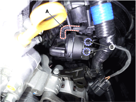
Disconnect the purge control solenoid valve connector (A).
|
|
3. |
Disconnect the vapor hoses (B) from the purge control solenoid valve.
|
|
4. |
Remove the bracket installation bolt (C), and then remove the valve
from the surge tank.
|
Tightening Torque :
9.8 - 11.8 N.m (1.0 - 1.2 kgf.m, 7.2 - 8.7 lb-ft)
|
|
| •
|
Install the component with the specified torques.
|
| •
|
Note that internal damage may occur when the component is dropped.
In this case, use it after inspecting.
|
|
| •
|
Be careful of foreign material not to flow into the valve.
|
|
|
1. |
Installation is reverse of removal.
|
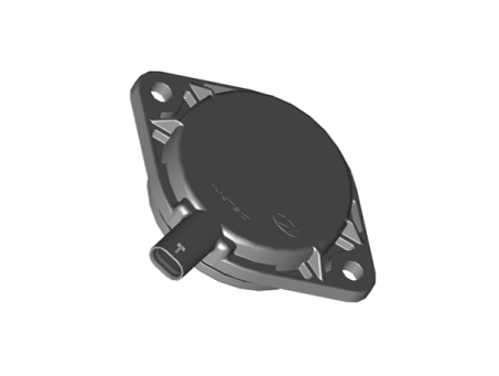
Variable Force Solenoid (VFS). Description and operation
CVVT (Continuous Variable Valve Timing) system advances or retards the valve
opening and closing timing of the intake or the exhaust valve in accordance
with the ECM control, calculated by the engine speed and the load. The CVVT
control causes a valve over-lap or under-lap between the intake valve and the
exhaust valve. This improves fuel efficiency, reduces exhaust gases (NOx, HC)
and enhances the engine performance, thanks to reduced pumping loss, internal
EGR (Exhaust Gas Recirculation) release, improved combustion stability, and
increased volumetric efficiency.The system consists of the CVVT Oil Control
Valve (OCV), which receives the ECM PWM (Pulse With Modulation) control signal
to change the path of the engine oil to supply to or discharge from the cam
phaser, the CVVT Oil Temperature Sensor (OTS), which measures the temperatures
of the engine oil, and the cam phaser, which varies the cam phasing by using
the hydraulic force of the engine oil.The oil delivered from the CVVT oil control
valve varies the phase angle of the cam, by rotating the rotor connected to
the camshaft of the cam phaser and causing the camshaft to rotate in the direction
of its engine running rotation (intake advanced / exhaust retarded) or the opposite
direction (intake retarded/ exhaust advanced).
Variable Force Solenoid (VFS). Specifications
Item
|
Specification
|
Coil Resistance (Ω)
|
6.0 - 7.0 [20°C (68°F)]
|
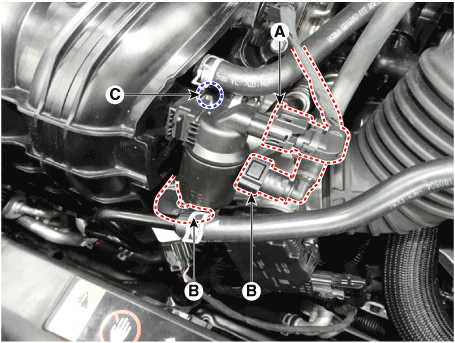
Variable Force Solenoid (VFS). Schematic diagrams

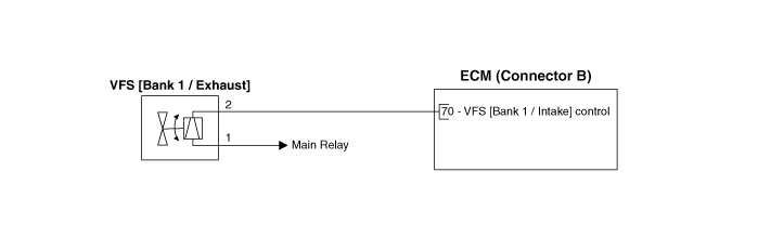
Harness Connector

Variable Force Solenoid (VFS). Repair procedures
|
1. |
Turn the ignition switch OFF.
|
|
2. |
Disconnect the OCV connector.
|
|
3. |
Measure resistance between the OCV terminals 1 and 2.
|
|
4. |
Check that the resistance is within the specification.
|
Specification : Refer to "Specification"
|
|
|
1. |
Turn the ignition switch OFF and disconnect the battery negative (-)
cable.
|
|
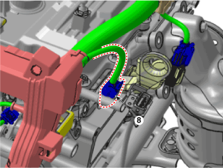
2. |
Disconnect the CVVT oil control valve connector (A).
|
|
3. |
Remove the installation bolt (B), and then remove the valve from the
engine.
|
Tightening Torque :
9.8 - 11.8 N.m (1.0 - 1.2 kgf.m, 7.2 - 8.7 lb-ft)
|
[Bank 1 / Intake]
[Bank 1 / Exhaust]
|
| •
|
Install the component with the specified torques.
|
| •
|
Note that internal damage may occur when the component is dropped.
In this case, use it after inspecting.
|
|
| •
|
Apply the engine oil to the valve O-ring.
|
|
|
1. |
Installation is reverse of removal.
|
Variable Intake Solenoid (VIS) Valve. Description and operation
Variable Intake manifold Solenoid (VIS) valve is installed on the intake manifold.
The VIS valve controls the vacuum modulator which activates a valve in the intake
manifold. The ECM opens or closes this valve according to engine condition (Refer
to below table).
Engine Condition
|
VIS Valve
|
Operation
|
Medium speed
|
Closed
|
Increasing engine performance in low engine speed by reducing intake interference
among cylinders
|
Low / High speed
|
Open
|
Minimizing intake resistance by shortening intake manifold length and increasing
area of air entrance
|
Variable Intake Solenoid (VIS) Valve. Specifications
Item
|
Specification
|
Coil resistance (Ω)
|
30.0 - 35.0 [20°C (68°F)]
|
Variable Intake Solenoid (VIS) Valve. Schematic diagrams
Harness Connector

Variable Intake Solenoid (VIS) Valve. Repair procedures
|
1. |
Turn the ignition switch OFF.
|
|
2. |
Disconnect the VIS valve connector.
|
|
3. |
Measure resistance between VIS valve terminals 1 and 2.
|
Specification : Refer to "Specification"
|
|
|
1. |
Turn the ignition switch OFF and disconnect the battery negative (-)
cable.
|
|
2. |
Disconnect the variable intake solenoid valve connector (A).
|
|
3. |
Disconnect the vacuum link (B) from the valve.
|
|
4. |
Disconnect the vacuum hoses (A) from the valve.
|
|
5. |
Remove the installation bolt (B), and then remove the valve from the
surge tank.
|
Tightening Torque :
9.8 - 11.8 N.m (1.0 - 1.2 kgf.m, 7.2 - 8.7 lb-ft)
|
|
| •
|
Install the component with the specified torques.
|
| •
|
Note that internal damage may occur when the component is dropped.
In this case, use it after inspecting.
|
|
| •
|
Be careful of foreign material not to flow into the valve.
|
|
|
1. |
Installation is reverse of removal.
|
Basic Troubleshooting Basic Troubleshooting Guide Customer Problem Analysis Sheet Basic Inspection Procedure Measuring Condition of Electronic Parts' Resistance The measured resistance at high temperature ...
Components and components location Components Location 1. Fuel tank 2. Fuel pump 3. Fuel filter 4. Fuel pump motor 5. Fuel level sender (FLS) 6. Fuel pressure regulator 7. Fuel tank air filter 8. Fuel ...
See also:
Troubleshooting
Trouble shooting Area of leakage occuring Area Applied engine ① Connecting part/under part of transfer case ② Connecting part of transmission Diesel 2.2 TCI ① Connecting part/under part of transfer ...
SS-B Solenoid Valve(ON/OFF). Description and Operation
Description SS-B solenoid valve is attached to the valve body and is an on/off solenoid valve that is used to change gears. SS-B Solenoid valve(ON/OFF) is installed at valve body. ...
Description and Operation
Description of ESC Electronic Stability Control (ESC) recognizes critical driving conditions, such as panic reactions in dangerous situations, and stabilizes the vehicle by wheel-individual braking and ...
 Hyundai Santa Fe (TM): Engine Control System


 Troubleshooting
 Fuel Delivery System