 Hyundai Santa Fe (TM): Specifications
| Specifications |
|
Item |
Specifications |
|
|
Engine type |
Gasoline 2.5 MPI |
|
|
Automatic transaxle type |
FF 6th Automatic transaxle (A6MF2-2) |
|
|
Drive type |
2WD / 4WD |
|
|
Gear ratio |
1st |
4.212 |
|
2nd |
2.637 |
|
|
3rd |
1.800 |
|
|
4th |
1.386 |
|
|
5th |
1.000 |
|
|
6th |
0.772 |
|
|
Reverse |
3.385 |
|
|
Final gear ratio |
3.917 |
|
|
Clutch type |
Torque converter |
|
|
Torque converter type |
3-element, 1-stage, 2-phase type |
|
|
Torque converter size |
Ø236 mm (9.2913 in) |
|
|
Oil pump system |
Mechanical internal gear pump |
|
|
Friction elements |
Clutch : 2EA |
|
|
Brake : 3EA |
||
|
OWC : 1EA |
||
|
Planetary gear |
3EA |
|
|
Fluid pressure balance piston |
2EA |
|
|
Accumulator |
4EA |
|
|
Solenoid valve |
7EA (VFS : 6EA, ON/OFF : 1EA) |
|
|
Shift lever position |
4 Range (P, R, N, D) |
|
|
Oil filter |
1EA |
|
※ VFS : Variable Force Solenoid
Sensors
Input Speed Sensor
▷ Type : Hall Effect Sensor
▷ Specifications
|
Items |
Specifications |
|
|
Operation condition (°C)°F |
(-40 to 150) -40 to 302 |
|
|
Output voltage (V) |
High |
1.18 - 1.68 |
|
Low |
0.59 - 0.84 |
|
Output Speed Sensor
▷ Type : Hall Effect Sensor
▷ Specifications
|
Items |
Specifications |
|
|
Operation condition (°C)°F |
(-40 to 150) -40 to 302 |
|
|
Output voltage (V) |
High |
1.18 - 1.68 |
|
Low |
0.59 - 0.84 |
|
Oil Temperature Sensor
▷ Type : Negative Thermal Coefficient (NTC)
▷ Specifications
|
Temp. [(°C)°F] |
Resistance (Ω) |
Min. |
Max. |
|
(-40) -40 |
48153 |
45301 |
51006 |
|
(-20) -4.0 |
15614 |
14785 |
16443 |
|
(0) 32.0 |
5887 |
5605 |
6168 |
|
(20) 68.0 |
2510.6 |
2401.9 |
2619.3 |
|
(40) 104.0 |
1199.6 |
1152.4 |
1246.7 |
|
(60) 140.0 |
612.3 |
590.3 |
634.2 |
|
(80) 176.0 |
329.5 |
318.7 |
340.3 |
|
(100) 212.0 |
186.0 |
180.4 |
191.6 |
|
(120) 248.0 |
109.7 |
106.1 |
113.2 |
|
(140) 284.0 |
67.16 |
64.82 |
69.5 |
|
(150) 302.0 |
53.24 |
51.32 |
55.16 |
Switch
Position switch
▷ Type : Combination of output signals from 4 terminals
▷ Specifications
|
Items |
Specifications |
|
Power supply (V) |
12 |
|
Output type |
Combination of output signals |
Solenoid Valves
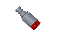
ON/OFF Solenoid Valve (SS-A)
▷ Control type : Normally low type
|
Shape |
Items |
Specifications |
|
|
Control voltage [V] |
9 - 16 |
|
Supply pressure [kpa (kgf/cm², psi)] |
490.33 (5.0, 71.12) |
|
|
Control pressure [kpa (kgf/cm² psi)] |
0 - 490.33 (0 - 5.0, 0 - 71.12) |
|
| Internal
resistance (Ω) |
10 - 11 |
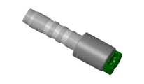
Clutch/Brake control VFS [T/CON]
▷ Control type : Normally low type
|
Shape |
Items |
Specifications |
|
|
Control current [mA] |
0 - 850 |
|
Supply pressure [kpa (kgf/cm² psi)] |
539.36 (5.5, 78.23) |
|
|
Control pressure [kpa (kgfcm², psi)] |
0 - 519.75 (0 - 5.3, 0 - 75.38) |
|
| Internal
resistance (Ω) |
4.8 - 5.4 |
Line Pressure Control VFS [Line pressure]
▷ Control type : Normally high type
|
Shape |
Items |
Specifications |
|
|
Control current [mA] |
0 - 850 |
|
Supply pressure [kpa (kgf/cm² psi)] |
539.36 (5.5, 78.23) |
|
|
Control pressure [kpa (kgf/cm², psi)] |
0 - 519.75 (0 - 5.3, 0 - 75.38) |
|
| Internal
resistance (Ω) |
4.8 - 5.4 |
Clutch/Brake control VFS [26/B,35R/C]
▷ Control type : Normally low type
|
Shape |
Items |
Specifications |
|
|
Control current [mA] |
0 - 1100 |
|
Supply pressure [kpa (kgf/cm², psi)] |
1569.06 (16, 227.57) |
|
|
Control pressure [kpa (kgf/cm², psi)] |
0 - 1569.06 (0 - 16, 0 - 227.57) |
|
| Internal
resistance (Ω) |
5.0 - 5.6 |
Clutch/Brake control VFS [UD/B, OD/C]
▷ Control Type : Normally high type
|
Shape |
Items |
Specifications |
|
|
Control current (voltage) [mA] |
0 - 1100 |
|
Supply pressure [kpa (kgf/cm², psi)] |
1569.06 (16, 227.57) |
|
|
Control pressure [kpa (kgf/cm², psi)] |
0 - 1569.06 (0 - 16, 0 - 227.57) |
|
| Internal
resistance (Ω) |
5.0 - 5.6 |
Solenoid Valve Operation Table
|
|
UD |
OD & LD |
35 R |
26B |
SS - A |
|
P |
● |
|
|
|
● |
|
N |
● |
|
|
|
● |
|
1 st |
|
Δ |
|
|
Δ |
|
2 nd |
|
● |
|
● |
|
|
3 rd |
|
● |
● |
|
|
|
4 th |
|
|
|
|
|
|
5 th |
● |
|
● |
|
|
|
6 th |
● |
|
|
● |
|
|
REV |
● |
|
● |
|
● |
● : Connected status
Δ : Connected at vehicle speed above 8km/h
Tightening Torques
|
Item |
N.m
|
kgf.m
|
lb-ft
|
|
Shift cable bracket mounting bolt |
14.7 - 21.6 |
1.5 - 2.2 |
10.8 - 15.9 |
|
Fixing nut of shift cable in the manual lever |
9.8 - 13.7 |
1.0 - 1.4 |
7.2 - 10.8 |
|
Automatic transaxle upper mounting bolt (TM→Eng) |
42.2 - 53.9 |
4.3 - 5.5 |
31.1 - 39.8 |
|
Automatic transaxle mounting bracket bolt |
88.3 - 107.9 |
9.0 - 11.0 |
65.1 - 79.6 |
|
Automatic transaxle support bracket mounting bolt |
58.9 - 78.5 |
6.0 - 8.0 |
43.4 - 57.8 |
|
Torque converter mounting bolt |
45.1 - 52.0 |
4.6 - 5.3 |
33.3 - 38.3 |
|
Automatic transaxle lower mounting bolt (Eng→TM) |
42.2 - 48.1 |
4.3 - 4.9 |
31.1 - 35.4 |
|
42.2 - 53.9 |
4.3 - 5.5 |
31.1 - 39.8 |
|
|
TCM mounting nut |
9.8 - 11.8 |
1.0 - 1.2 |
7.2 - 8.7 |
|
Input shaft speed sensor mounting bolt |
9.8 - 11.8 |
1.0 - 1.2 |
7.2 - 8.7 |
|
Output shaft speed sensor mounting bolt |
9.8 - 11.8 |
1.0 - 1.2 |
7.2 - 8.7 |
|
Shift lever assembly bolt |
8.8 - 13.7 |
0.9 - 1.4 |
9.4 - 10.1 |
|
Position switch mounting bolt |
9.8 - 11.8 |
1.0 - 1.2 |
7.2 - 8.7 |
|
Valve body cover mounting bolt |
11.8 - 13.7 |
1.2 - 1.4 |
8.7 - 10.1 |
|
ATF drain plug |
33.3 - 43.1 |
3.4 - 4.4 |
24.6 - 31.8 |
|
Starter mounting bolt |
49.0 - 63.7 |
5.0 - 6.5 |
36.2 - 47.0 |
| Lubricants |
Fluid
|
ATF Grade |
Recommended |
Allowed |
|
ATF SP-Ⅳ |
SK ATF SP4M-1, MICHANG ATF SP4M-1,NOCA ATF SP4M-1, Hyundai Genuine ATF SP4M-1 |
|
|
ATF Quantity |
6.7L (1.77 U.S gal., 7.08 U.S.qt., 5.90 Imp.qt.) |
|
Sealant
|
Item |
Specified
sealant |
|
Torque converter housing |
LOCTITE FMD-5460 |
 Troubleshooting
▶Fault Diagnosis Features a fail-safe mechanism that provides "limp-home" 4th gear hold to enable the vehicle to be driven to the owner's home or dealer shop. • Fail-Safe ...
 Special service tools
Special Service Tools Tool (Number and Name) Illustration Use 09200-3N000 Engine support fixture (Beam) Removal and installation of the transaxle.Use this beam (SST No. : 09200-3N000) with the supporter ...
See also:
Automatic turn off function
The interior lights automatically turn off approximately 20 minutes after the ignition switch is turned off. If your vehicle is equipped with the theft alarm system, the interior lights automatically turn ...
ETC (Electronic Throttle Control) System. Schematic Diagrams
Circuit Diagram ...
Special service tools
Special Tools Tool (Number and name) Illustration Use 09977-3R000 Clutch bolt remover Removal and installation of clutch bolt ...


