 Hyundai Santa Fe (TM): Cruise Control System (CC)
Description and operation
| Description |
The cruise control system is engaged by the cruise "ON/OFF" main switch located
on right of steering wheel column. The system has the capability to cruise,
coast, accelerate and resume speed.
It also has a safety interrupt, engaged upon depressing brake or shifting select
lever.
The ECM is the control module for this system. The main components of cruise
control system are mode control switches, transmission range switch, brake switch,
vehicle speed sensor, ECM and ETS motor that connect throttle body.
The ECM contains a low speed limit which will prevent system engagement below
a minimum speed of 40km/h (25mph).
The operation of the controller is controlled by mode control switches located
on steering wheel.
Transmission range switch and brake switch are provided to disengage the cruise
control system. The switches are on brake pedal bracket and transmission. When
the brake pedal is depressed or select lever shifted, the cruise control system
is electrically disengaged and the throttle is returned to the idle position.
| Cruise main switch (CRUISE) |
The cruise control system is engaged by pressing the cruise "ON/OFF" main switch.
Pressing the cruise "ON/OFF" main switch again releases throttle, clears cruise
memory speed, and puts vehicle in a non-cruise mode.
| Set/Coast switch (SET/‚Äď) |
The "SET/‚Äď" switch located on right of steering wheel column has two functions.
The set function - Push the "SET/‚Äď" switch and release it at the desired speed.
The SET indicator light in the instrument cluster will illuminate. Release the
accelerator pedal. The desired speed will automatically be maintained.
The coast function - Push the "SET/‚Äď" switch and hold it when the cruise control
is on. The vehicle will gradually slow down. Release the switch at the desired
speed. The desired speed will be maintained.
Push the "SET/‚Äď" switch and release it quickly. The cruising speed will decrease
by 2km/h or 1mph.
| Resume/Accel switch (RES/+) |
The "RES/+" switch located on right of steering wheel column has two functions.
The resume function - If any method other than the cruise ‚ÄúON/OFF‚ÄĚ main switch
was used to cancel cruising speed temporarily and the system is still activated,
the most recent set speed will automatically resume when the "RES/+" switch
is pushed. It will not resume, however, if the vehicle speed has dropped below
approximately 40km/h (25mph).
The accel function - Push the "RES/+" switch and hold it when the cruise control
is on. The vehicle will gradually accelerate. Release the switch at the desired
speed. The desired speed will be maintained.
Push the "RES/+" switch and release it quickly. The cruising speed will increase
by 2km/h or 1mph.
| Cancel switch (CANCEL) |
The cruise control system is temporarily disengaged by pushing the "CANCEL"
switch.
Cruise speed canceled by this switch can be recovered by pushing the "RES/+"
switch.
Troubleshooting
| Trouble Symptom Charts |
| Trouble Symptom 1 |
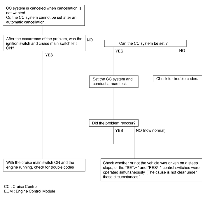
| Trouble Symptom 2 |
|
Trouble symptom |
Probable cause |
Remedy |
|
The set vehicle speed varies greatly upward or downward "Surging" (repeated alternating acceleration and deceleration) occurs after setting |
Malfunction of the vehicle speed sensor circuit |
Repair the vehicle speed sensor system, or replace the part |
|
Malfunction of ECM |
Check input and output signals at ECM |
| Trouble Symptom 3 |
|
Trouble symptom |
Probable cause |
Remedy |
|
The CC system is not canceled when the brake pedal is depressed |
Damaged or disconnected wiring of the brake pedal switch |
Repair the harness or replace the brake pedal switch |
|
Malfunction of the ECM signals |
Check input and output signals at ECM |
| Trouble Symptom 4 |
|
Trouble symptom |
Probable cause |
Remedy |
|
The CC system is not canceled when the shift lever is moved to the "N" position
(It is canceled, however, when the brake pedal is depressed) |
Damaged or disconnected wiring of inhibitor switch input circuit |
Repair the harness or repair or replace the inhibitor switch |
|
Improper adjustment of inhibitor switch |
||
|
Malfunction of the ECM signals |
Check input and output signals at ECM |
| Trouble Symptom 5 |
|
Trouble symptom |
Probable cause |
Remedy |
|
Cannot decelerate (coast) by using the "SET/‚Äď" switch |
Temporary damaged or disconnected wiring of "SET/‚Äď" switch input circuit |
Repair the harness or replace the "SET/‚Äď" switch |
|
Malfunction of the ECM signals |
Check input and output signals at ECM |
| Trouble Symptom 6 |
|
Trouble symptom |
Probable cause |
Remedy |
|
Cannot accelerate or resume speed by using the "RES/+" switch |
Damaged or disconnected wiring, or short circuit, or "RES/+" switch input
circuit |
Repair the harness or replace the "RES/+" switch |
|
Malfunction of the ECM signals |
Check input and output signals at ECM |
| Trouble Symptom 7 |
|
Trouble symptom |
Probable cause |
Remedy |
|
CC system can be set while driving at a vehicle speed of less than 40km/h
(25mph), or there is no automatic cancellation at that speed |
Malfunction of the vehicle-speed sensor circuit |
Repair the vehicle speed sensor system, or replace the part |
|
Malfunction of the ECM signals |
Check input and output signals at ECM |
| Trouble Symptom 8 |
|
Trouble symptom |
Probable cause |
Remedy |
|
The cruise main switch indicator lamp does not illuminate (But CC system
is normal) |
Damaged or disconnected bulb of cruise main switch indicator lamp |
Repair the harness or replace the part. |
|
Harness damaged or disconnected |
Schematic diagrams
| System Block Diagram |
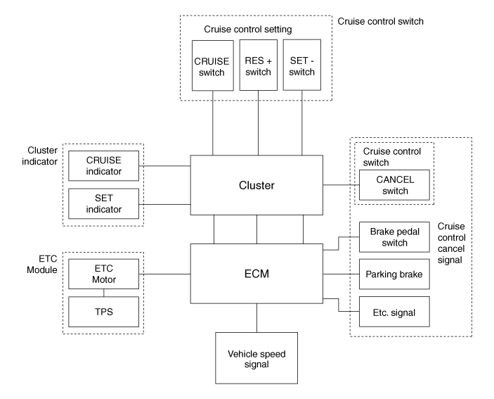
Component Parts And Function Outline
|
Component part |
Function |
|
|
Vehicle-speed sensor, ESP/ABS Control Module |
Converts vehicle speed to pulse. |
|
|
ECM |
Receives signals from sensor and control switches. |
|
|
Cruise control indicator |
Illuminate when CRUISE main switch is ON (Built into cluster) |
|
|
Cruise Control switches |
CRUISE switch |
Switch for automatic speed control power supply. |
|
Resume/Accel switch (RES +) |
Controls automatic speed control functions by Resume/Accel switch (Set/Coast
switch) |
|
|
Set/Coast switch (RES -) |
||
|
Cancel switches |
Cancel switch |
Sends cancel signals to ECM. |
|
Brake-pedal switch |
||
|
Transaxle range switch (A/T) |
||
|
ETC Motor |
Regulates the throttle valve to the set opening by ECM. |
|
* ETC Motor : Electronic Throttle Control Motor
Cruise Control (CC) Switch. Components and components location
| Components |
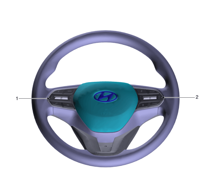
| 1. Remote control
switch (Audio swtich) |
2. Remote control
switch (Cruise control switch) |
Cruise Control (CC) Switch. Schematic diagrams
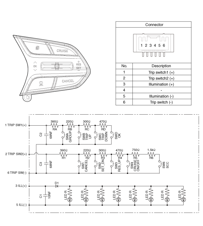
| Circuit Diagram |
[Trip/Cruise/Smart Cruise]
Cruise Control (CC) Switch. Repair procedures
| Inspection |
| 1. |
Check for resistance between terminals in left switch position.
[Audio/Bluetooth]
|
| 2. |
Check for resistance between terminals in right switch position.
[Trip/Cruise]
|
| Removal |
| 1. |
Disconnect the negative (-) battery terminal.
|
| 2. |
Remove the driver airbag module.
(Refer to Restraint - "Driver Airbag (DAB) Module and Clock Spring")
|
| 3. |
Remove the steering wheel.
(Refer to Steering System - "Steering Column and Shaft")
|
| 4. |
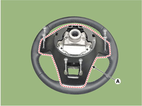
Remove the steering wheel cover (A) after loosening the screws.
|
| 5. |
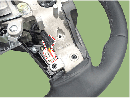
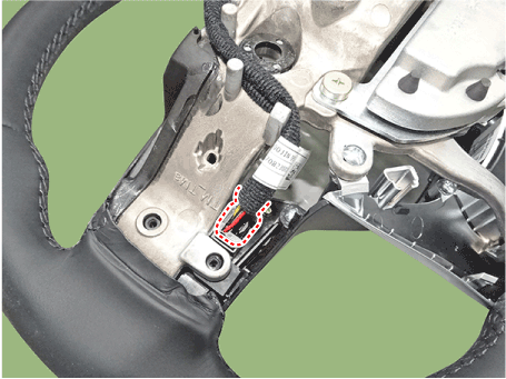
Loosen the screws and then disconnect the steering wheel remote control
switch connector.
|
| 6. |
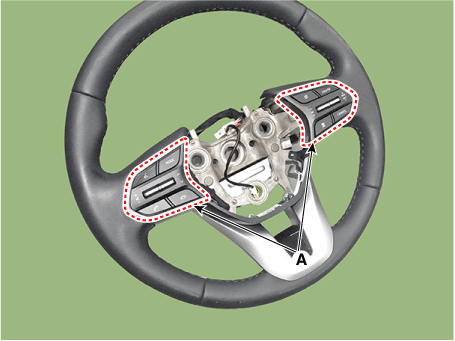
Remove the remote control switchs (A).
|
| Installation |
| 1. |
Install the remote control switch on the steering wheel.
|
| 2. |
Install the steering wheel.
|
| 3. |
Reconnect the remote control switch connector and airbag connectors.
|
| 4. |
Install the driver airbag module.
|
| 5. |
Connect the negative (-) battery terminal.
|
 Surround View Monitor (SVM)
Description and operation Description Surround View Monitor (SVM) is the system that allows video monitoring of 360 degrees around the vehicle. The system includes 4 ultra optical camera mounted around ...
 Rear View Monitor (RVM)
Description and operation Description Back view camera will activate when the backup light is ON with the ignition switch ON and the shift lever in the R position. This system is a supplemental system ...
See also:
Ignition Coil. Specifications
Specification Item Specification Primary Coil Resistance (Ω) 0.79 ¬Ī 15% [20¬įC (68¬įF)] Secondary Coil Resistance (kΩ) 7.0 ¬Ī 15% [20¬įC (68¬įF)] ...
Components and Components Location
Components 1. Cooling fan 2. Radiator upper hose 3. Radiator lower hoseRadiator cap 4. Radiator 5. Condenser 6. Air guard 7. Over flow hose 8. Reservior tank ...
Troubleshooting
Troubleshooting Problem Symptoms Table Use the table below to help you find the cause of the problem. The numbers indicate the priority of the like cause of the problem. Check each part in order. If necessary, ...

