Description and operation
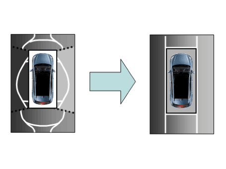
Surround View Monitor (SVM) is the system that allows video monitoring of 360
degrees around the vehicle. The system includes 4 ultra optical camera mounted
around the vehicle (front, both sides, rear).
The video from these cameras are applied with distortion compensation, time
point conversion, and video merging technologies to provide sky-view image of
the vehicle's surrounding area, as well as various other view modes.
The SVM System provides video feed of the vehicle's surrounding area while parking
or during low speed driving to the driver to enhance safety and driver's convenience.
In addition, the system also displays video image of vehicle's surrounding area,
and includes steering wheel synchronized guide line indication, front and rear
object warning, and A/S (including In-Line) tolerance compensation features.
It's a system that displays the video, from ultra optical cameras mounted on
4 sides of the vehicle, on the Head Unit Screen. It shows 360 degrees sky-view
image of the vehicle's surrounding area, as well as various other view modes.
The SVM System provides video feed of the vehicle's surrounding area while the
vehicle is parked or during low speed driving to the driver to enhance safety
and driver's convenience.
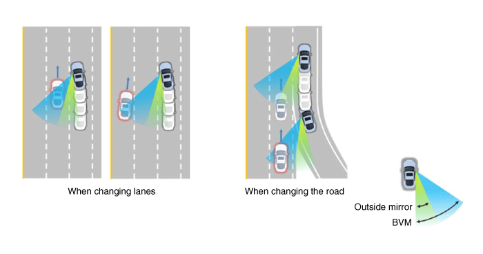
Blind-spot View Monitor (BVM)
Blind-spot View Monitor (BVM) is a driving safety system that helps provide
a more comprehensive views on areas which is not usually visible by the side
mirrors when the vehicle tries to change the lane.
|
The BVM system provides a driver a more comprehensive view which is
not usually visible by the side mirrors in certain situations like swithing
drive lanes. The system helps to avoid any blind spot mishaps.
|
| – |
The rear side view is displayed in the cluster screen when the turning
lights are in operation as the turn signal light switch goes up and
down by the driver.
|
| – |
The SVM also provides an edited view of the left side/ right side without
adding more cameras.
|
| – |
It helps minimize the distraction of the driver by displaying the rear
side view that is usually hard to see.
|
| •
|
The video will be played even though the side mirrors are folded.
But it does not provide a proper view of the surroundings.
|
| •
|
The video quality may be lower than the SVM video as the size
of the original image has to be adjusted to fit the cluster.
|
| •
|
The screen may temporarily fades out with changes in light conditions
during daytime or with a sunrise or a sunset. Or when the car
enters the tunnel.
|
| •
|
The view of the surrounding objects provided by the system may
look far away than views that are obtained by the side mirrors.
|
| •
|
The brightness of the rear side video may change due to a mode
switching delay of the SVM/BVM.
|
|
|
1. |
Display Vehicles Surrounding in Video
The surrounding area video display function displays the 360 degrees
video image captured through 4 cameras to the driver through the Head
controller Screen while the vehicle is moving at low speed or going
reverse. The SVM System displays total of 8 video modes for displaying
surrounding video based on the vehicle driving state and the driver's
selection.
|
|
2. |
Guide Line Indication & Steering Wheel Synchronized Feature
The Guide Line Indication & Steering Wheel Synchronized Feature is the
function that assists the driver in parking by synchronizing the steering
wheel with the rear view video display marked with a guide line to help
anticipate the direction of the vehicle going reverse.
|
|
3. |
Front/Rear Object Warning (Obstacle Detection Feature)
The system receives obstacle warning signal from the PAS or SPAS sensors
mounted on the front/rear of the vehicle and displays the obstacle location
on the SVM Head Unit Screen.
|
|
4. |
Tolerance Compensation (including A/S)
Manual Tolerance Compensation Software is embedded in the SVMECM to
compensate the SVM deviation that may occur due to assembly line installation
tolerance. You must first setup proper work environment in order to
perform correct tolerance compensation.
|
Main Features
No
|
Main Features
|
Detailed Description
|
Notes
|
1
|
8 View Mode Display
|
| •
|
4 Front & 4 Rear View Mode Display
|
|
Merged Video Display of 8 Modes
|
2
|
Front Assist Mode Selection Feature
|
| •
|
Display only the Front Mode by using the Front Mode Selection
Switch
|
|
Same as the PAS SVM Switch
|
3
|
Rear Steering Synchronized Parking Guide Line Display
|
| •
|
Displays Parking Guide Line by synchronizing with the steering
wheel when going reverse.
|
|
Display over the Rear Video
|
4
|
PAS Obstacle Indication
|
| •
|
Display obstacle warning from rear and front PAS
|
|
Display both on the Cluster and the Head Unit
|
5
|
User Setting Option
|
| •
|
Select Steering Wheel Synchronized Guide Line Indication
|
| •
|
Select Front/Rear Obstacle Indication
|
| •
|
Select Initial Front/Rear View Screen
|
|
Provides additional screen settings
|
6
|
Assembly Line & A/S Tolerance Compensation Feature
|
| •
|
Compensation - Tolerance Compensation for camera installation
deviation and assembly line tolerance is required
|
|
Compensation function recognition logic applied
|
SVM Mode Entry Conditions
The vehicle information is accessed regularly, even after entering SVM mode.
When the conditions are met, conversion from front mode to rear mode is available,
and vice versa.
When the mode is converted, the view displayed on the screen can be the initial
view or the previous view depending on the conditions.
If the mode for conversion is the initial entry, the default view is selected
based on the front or rear. If a continuous front-rear conversion mode occurs
as forward and backward movement are repeated for parking, the previous view
is recalled and displayed.
| – |
Initial Entry: When the rear and front mode view in SVM mode is displayed
on the screen for the first time
|
| – |
Re-entry: When switching from SVM mode to another mode, without turning
off SVM, and returning to the previous mode
(e.g. Rear → Front → Rear: Re-enter rear mode / Front → Rear → Front:
Re-enter front mode)
|
Switch mode
|
Vehicle speed
|
Gear
|
SVM Switch
|
Display view
|
Rear → Front
|
below 15 kph
|
R Range or P Range excluded
|
ON
|
Initial Entry: Front view set in the initial view mode option
|
Re-entry: The last view mode displayed in the previous front mode
|
Front → Rear
|
Irrelevant
|
Reverse Gear
|
Irrelevant
|
Initial Entry: Rear view set in the initial view mode option
|
Re-entry: The last view mode displayed in the previous rear mode
|
SVM Mode Disengagement
If the conditions below are satisfied while in SVM mode, the SVM is turned OFF
and no video is displayed.
OFF Mode
|
Vehicle speed
|
Gear
|
SVM Switch
|
Notes
|
Front mode
|
over 20 kph
|
R Range or P Range
|
OFF
|
If any of the three conditions are satisfied
|
Rear mode
|
Irrelevant
|
Except R gear
|
Irrelevant
|
If any of the two conditions are satisfied
|
SVM Options
Considering the user's convenience, the SVM provides three options for the user
to select.
The window for changing options (parking guide settings) is displayed by the
AVN. Only the changed options are forwarded to the SVM controller through M_CAN.
These three options are applied as soon as they have been selected by the user.
Based on the conditions, the initial views displayed are as follows.
Option
|
Function
|
Default setting
|
Guideline steering interlocking
|
Interlocks with steering to display the driving direction of the vehicle
during parking.
|
Classification code
|
Close range warning indicator
|
Indicates front and rear obstacle detection
|
Classification code
|
Initial view mode setting
|
Default view displayed when entering SVM mode
|
Front + around view
|
Rear + around view
|
Operations for Guideline Steering Interlocking Indications
The indication for the guideline steering interlocking trace uses the steering
wheel angle value periodically received by the SVM controller through C-CAN.
A rear area that displays a 130 degree image of the rear mode (two-split mode)
and a wide view are displayed with the expected car movement trace.
|
1. |
View modes for guideline steering interlocking indications
Mode
|
View
|
Notes
|
Rear
|
Rear wide view + Top view
|
|
Rear top view + Top view
|
|
Rear corner view + Top view
|
|
|
|
2. |
Specifications for guideline steering interlocking trace lines
Number
|
Distance
|
Color
|
â‘
|
0.5 m
|
Red
|
â‘¡
|
1 m
|
Yellow
|
â‘¢
|
3 m
|
Yellow
|
â‘£
|
Bumper left side end + 0.3 m
|
Yellow
|
⑤
|
Bumper right side end + 0.3 m
|
Yellow
|
|
|
3. |
Indications for neutral trace lines
If the steering angle is neutral, the neutral trace line is indicated
in blue, which shows the expected movement trace of the car.
This line is displayed with the guideline steering interlocking trace
line and is also a fixed line that is not interlocked with the steering
angle operation.
|
SVM system input/output
|
1. |
Camera input
Category
|
Specification
|
Lens angle of view
|
190°
|
Angle of view
|
Horizontal
|
192°
|
Vertical
|
137°
|
Provided function
|
Original wide angle image is provided
|
(No additional functions)
|
Applied position
|
Applied to front/rear/left/right cameras
|
|
|
2. |
SVM image display
The images received from the 4 cameras mounted on the vehicle go through
the image distortion correction logic and the image merging process.H/UNIT
displays these images toghether with other additional features such
as the parking guidelines linked with steering wheel on the AVN screen.
|
|
3. |
Parking/view button
It is used as a control input signal to operate the front view mode
function with the ignition switch ON.
|
|
4. |
Ignition input
SVM controller displays the image only in the IGN1 ON and limits the
image display with the SVM OFF in the IGN1 OFF.
SVM controller uses the signal which is input to the IGN pin or B-CAN
message routed from the IGPM (gateway) to C-CAN to judge the IGN1 ON/OFF.
|
|
5. |
Chassis CAN input (C_CAN)
SVM controller receives the vehicle state information through the C_CAN
to determine the operation of SVM major functions.
|
|
6. |
Multimedia CAN input/output
Relevant information is processed by receiving the M-CAN signal routed
from the IGPM (gateway) to C-CAN.
The routed M-CAN signal communication aims to transmit and receive the
below information.
|
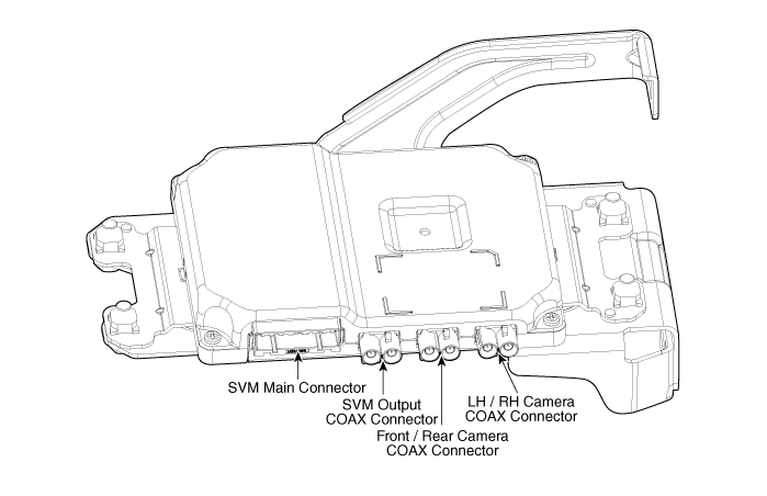
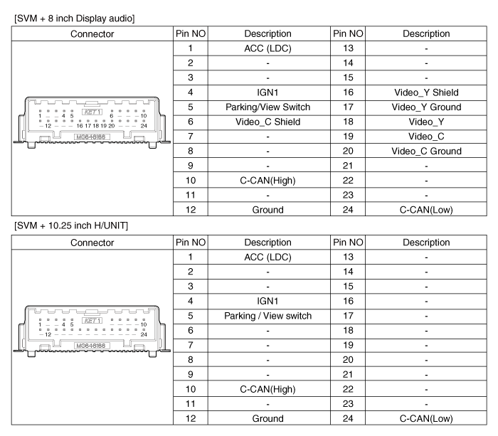
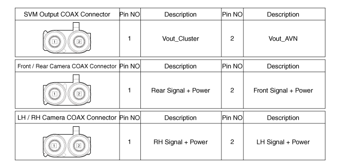
Components and components location
Troubleshooting
| 1) |
After replacing controller, always check that the system operates
properly.
|
| 2) |
If the failure persists after replacing the controller, do not
replace the controller.
|
|
|
1. |
Inspection by DTC Code
Symptom
|
Probable Cause
|
Remedy
|
1. Single DTC code appearance
|
Loose connector relevant to a certain DTC code
|
1) Check connection status and reconnect the connector.
|
Tolerance compensation not completed
|
1) DTC code appearance (B103000)
2) Perform tolerance compensation.
|
Disconnected wiring
|
1) Inspect for conductivity of relevant area of DTC and wiring.
- DTC code generated (B16B700/B16B800/B16B900/B16BA00/C161600/B162C00)
|
Faulty wiring connector
|
1) Check for bent or damaged wiring connector pin.
2) DTC code generated (B16B700/B16B800/B16B900/B16BA00
|
Faulty controller connector
|
1) Check for bent or damaged controller connector pin.
2) DTC code generated (B16B700/B16B800/B16B900/B16BA00)
|
Faulty controller single unit or camera
|
1) Check basic operation and DTC on Diagnostic tool.
2) DTC code generated (B16B700/B16B800/B16B900/B16BA00)
|
2. Multiple DTC codes appearance
|
Loose SVM main connector
|
1) Check connection status and reconnect the connector.
|
Disconnected wiring
|
1) Camera power
- In case of 6V or below, inspect relevant wiring.
2) ACC/IGN power
- In case of 7.5V or below, inspect relevant wiring.
3) Parking/view button
- In case of 1.75V or higher with the switch ON, inspect relevant
wiring.
|
Faulty wiring connector
|
1) Check for bent wiring connector pin or interference in neighboring
parts.
2) DTC code generated (B16B700/B16B800/B16B900/B16BA00)
|
Faulty controller connector
|
1) Check for bent controller connector or interference in neighboring
parts.
2) DTC code generated (B16B700/B16B800/B16B900/B16BA00)
|
Faulty controller single unit
|
1) If failure recurs after the items above are confirmed normal,
replace SVM.
|
|
|
2. |
Inspection for Defect in SVM Performance (Image Output)
Symptom
|
Probable Cause
|
Remedy
|
1. No image output :
Black screen, Blue screen, Green screen
|
Loose controller or SVM main connector
|
1) Check connection status and reconnect the connector.
|
Disconnected controller or SVM wiring
|
1) Inspect for conductivity of ACC / IGN / V-OUT / M-CAN terminal
wiring
|
Faulty IPM (SJB)
|
1) Check power of ACC / IGN terminals : In case of 7.5V or below,
inspect IPM (SJB)
|
Faulty controller or SVM
|
1) If failure recurs after the items above are confirmed normal,
replace controller or SVM camera.
|
2. Abnormal image output :Noise on screen / lines / cracked display
/ unable to change display
|
Loose main connector
|
1) Check connection status and reconnect the connector.
|
Disconnected or short-circuited wiring
|
1) Inspect the wiring relevant to DTC appearance.
|
Faulty tolerance compensation
|
1) If the SVM image display is cracked even though the camera display
is normal, execute tolerance compensation again.
|
Faulty camera
|
1) If both camera display and SVM image display are cracked, inspect
the camera.
|
Faulty IPM (SJB)
|
1) In case of DTC code (C161600) appearance, inspect IPM (SJB).
|
Faulty console switch
|
1) Inspect parking/view button.
- In case of 1.75V or higher with the switch ON, replace the switch.
|
Faulty controller or SVM camera
|
1) If failure recurs after the items above are confirmed normal,
replace controller or SVM camera.
|
|
|
3. |
Inspection for Faulty PAS Warning Display & Parking Guideline
Symptom
|
Probable Cause
|
Remedy
|
1. Faulty PAS warning display & faulty parking guideline
|
H/UNIT option information not configured
|
1) Check and modify AVN option configuration status.
|
Loose main connector
|
1) Check connection status and reconnect the connector.
|
Faulty IPM (SJB)
|
1) Check that Parking Assist System (PAS) and Steering wheel Angle
Sensor (SAS) are normal.
2) Inspect IPM (SJB).
|
Faulty controller or SVM
|
1) If failure recurs after the items above are confirmed normal,
replace controller or SVM.
|
|
Repair procedures
Tolerance Compensation
Tolerance compensation compensates for the error margins of surround view video
that occur due to the installation tolerance when the four cameras that comprise
the SVM system are installed.
You must carry out tolerance compensation if you do any of the following.
| – |
Remove and install a wide camera.
|
| – |
Conduct a body task that causes the focus of the wide camera to change,
such as a trunk task.
|
| – |
Replace the door mirror that has a wide camera.
|
| – |
Replace the SVM Controller.
|
Tolerance Compensation Environments
|
There are two types of tolerance compensation [manual tolerance compenstation]
and [automatic tolerance compensation].
The service center with the SVM exclusive workshop performs [automatic
tolerance compensation].
The maintenance environment lacking an SVM exclusive workshop performs
[manual tolerance compensation].
|
The Procedure of Manual Tolerance Compensation
|
1. |
Advanced preparations will be made according to the following.
| –
|
Confirm that the car hood, trunk and door are closed.
|
| –
|
The door is closed after getting in on the passenger side.
|
| –
|
Unfold the side mirror if it is folded in.
|
| –
|
Put the gear into neutral.
|
| –
|
In the preparation stage ahead of time an exhaust inhaler should
not be installed as it can block the view of the rear camera.
|
| –
|
Also, the exhaust from the exhaust pipe can create a smokescreen
blocking rear footage, therefore after using a fan to clear
the exhaust the compensation work should be performed while
in IGN (ignition).
|
| –
|
The foot brake or electro-mechanical parking brake should be
engaged to prevent the car from moving.
|
|
|
2. |
The following processes will be performed to confirm whether or not
the SVM ECU and camera are working properly before engaging tolerance
compensation mode.
| –
|
Confirm that the initially set up video is showing up. (front
view footage while the gear is in neutral + top view footage)
|
| –
|
Confirm that footage from the front, back, left and right is
showing up properly.
|
| –
|
When the footage appears properly, the tolerance compensation
mode will be engaged, and when footage is not showing up clearly
or does not show up at all the part will have to be replaced.
|
|
|
3. |
Install around the vehicle by referring to the guide that was provided
along with the compensation scales (2), compensation standard line boards
(2), and compensation target boards (4).
|
When centering the wheels on the compensation standards line
board, the A-type and B-type must be centered separately.
Caution should be taken because the center location of the white
and black compensation plate consist of standard coordinates
the accuracy(distance / right-angles) are very important.
|
– |
The front and rear / left and right centering should
be maintained within a deviation of 3cm.
|
|
– |
When centering the vehicle the rotation deviation should
be maintained within 1 degree on the side.
|
|
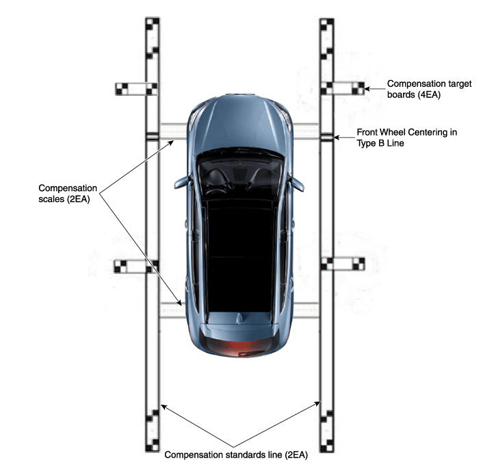
|
|
4. |
Keep the IG on while the car is stopped, confirm the location of the
gear stick is on ‘N’ and engage the parking brake on a flat area.
|
|
5. |
Perform the work with the parking/view switch in the vehicle set to
‘ON.’
|
|
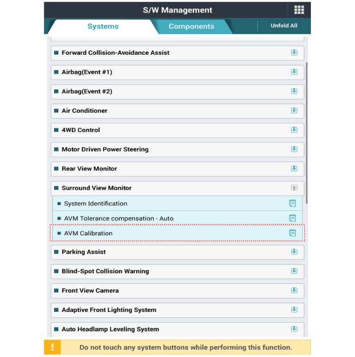
6. |
Perform SVM Calibration according to GDS diagnostics display.
|
|
7. |
Proceed with the AVM calibration according to the GDS screen.
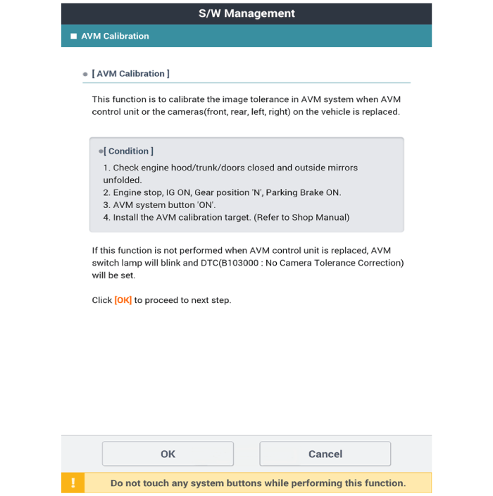
|
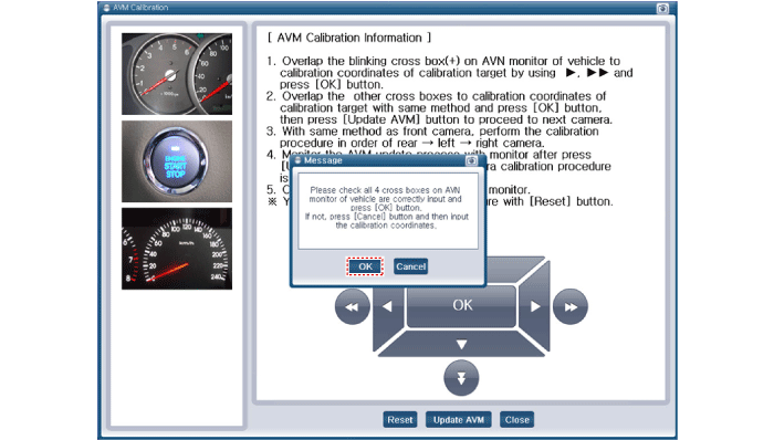
• |
Before matching the calibration point : "+" blinks in
green color.
|
|
• |
When you click [OK] after matching the calibration point
: "+" turns on in red color.
|
|
• |
After matching 4 forward correction points, click [OK]
button and click [Update AVM] button to move to the
next camera calibration.
|
|
• |
Perform the calibration in the order of front -> rear
-> left -> right camera.
|
|
|
|
8. |
After checking the vehicle and calibration line on the AVN monitor screen
to see if the calibration has been performed properly, press the [OK]
button.
When calibration has not been performed properly, press the [Cancel]
button to match the calibration points again.
[AVN Monitor]
[GDS Screen]
|
Surround View Monitor (SVM) Unit. Components and components location
Surround View Monitor (SVM) Unit. Repair procedures
|
1. |
Disconnect the negative (-) battery terminal.
|
|
2. |
Remove the carash pad lower panel.
(Refer to Body - "Crash Pad Lower Panel")
|
|
3. |
Remove the crash pad center panel.
(Refer to Body - "Crash Pad Center Panel")
|
|
4. |
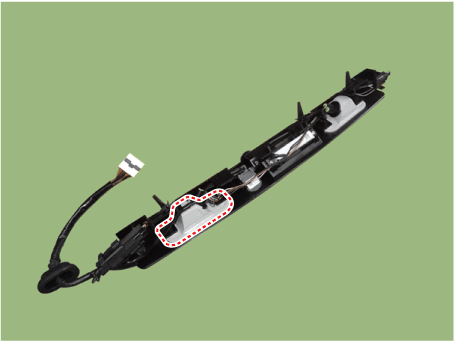
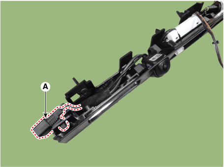
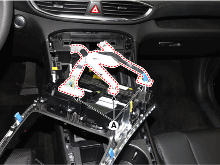
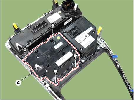
Disconnect the SVM unit connector (A).
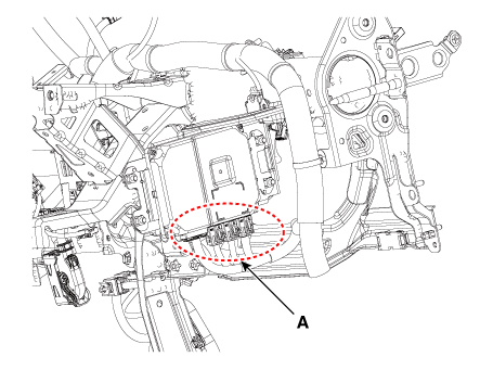
|
|
5. |
Loosen the mounting nuts and remove the SVM Unit (A).
|
|
2. |
Install the crash pad center panel.
|
|
3. |
Connect the negative (-) battery terminal.
|
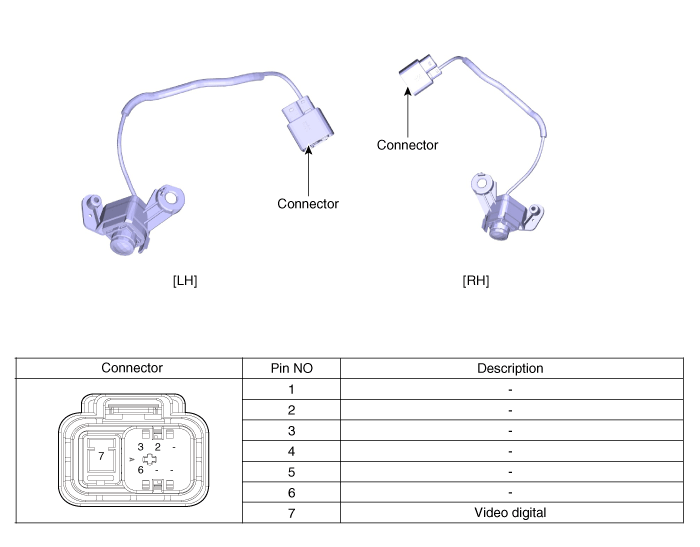
Surround View Monitor (SVM) Camera. Components and components location
[Ultra Optical Camera - RH/LH]
[Ultra Optical Camera - Front]
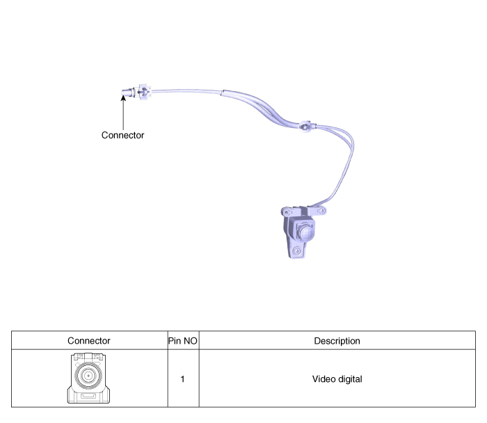
[Ultra Optical Camera - Rear]
Surround View Monitor (SVM) Camera. Repair procedures
| •
|
In case of bad quality or poor focus, be sure to check the camera
lense surface condition and foreign materials.
|
|
Front Camera
|
1. |
Disconnect the negative (-) battery terminal.
|
|
2. |
Remove the front bumper cover.
(Refer to Body - "Front Bumper Cover")
|
|
3. |
Remove the pantocscpic camera after loosening the mounting screws and
connector.
|
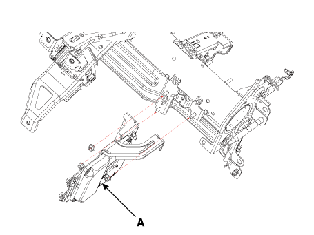
Rear Camera
|
1. |
Remove the tailgate trim.
(Refer to Body - "Tailgate Trim")
|
|
2. |
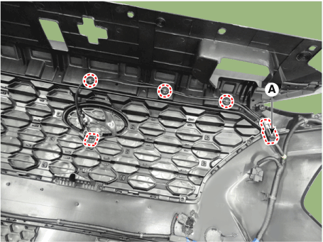
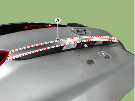
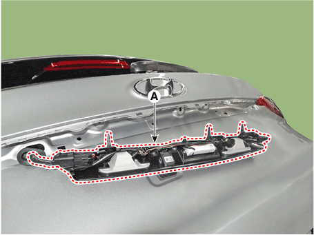
Remove the tailgate ganish (A).
|
|
3. |
Remove the tailgate switch assembly.
|
|
4. |
Remove the license lamp LH.
|
|
5. |
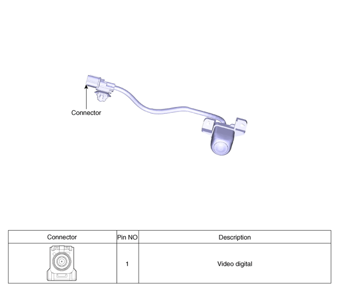
Disconnector the connector (A) and then remove the rear view camera.
|
Left/ Right Camera
|
1. |
Disconnect the negative (-) battery terminal.
|
|
2. |
Remove the mirror.
(Refer to Power Door Mirror - "Power Door Mirror Actuator")
|
|
3. |
Remove the outside mirror cover.
(Refer to Power Door Mirror - "Power Door Mirror Actuator")
|
|
4. |
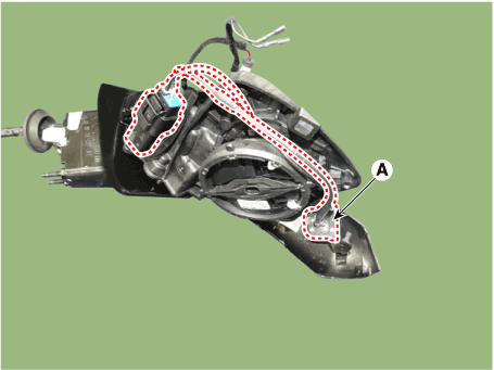
Disconnect the camera conenctor and then remove the camera (A).
|
Front Camera
|
1. |
Install the front camera.
|
|
2. |
Install the front bumper cover.
|
Rear Camera
|
1. |
Install the rear camera.
|
|
2. |
Install the tail gate switch assemblyl.
|
|
3. |
Install the tail gate trim.
(Refer to Body - "Tail Gate Trim")
|
Left/Right Camera
|
1. |
Install the left/right camera.
|
|
2. |
Install the door mirror.
|
Parking/View Switch. Repair procedures
| •
|
When removing with a flat-tip screwdriver or remover, wrap protective
tape around the tools to prevent damage to components.
|
| •
|
Put on gloves to prevent hand injuries.
|
|
| •
|
Take care not to bend or scratch the trim and panels.
|
|
|
1. |
Disconnect the negative (-) battery terminal.
|
|
2. |
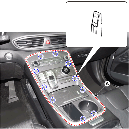
Remove the console upper cover (A).
|
|
3. |
Disconnect the console upper cover connectors (A).
|
|
4. |
Loosen the mounting screws and remove parking/view switch (A)
|
|
1. |
Install the parking/view switch.
|
|
2. |
Install the console upper cover.
|
|
3. |
Connect the negative (-) battery terminal.
|
Description and operation Description • PDW consists of 8 sensors (front : 4 units, rear : 4 units) that are used to detect obstacles and transmit the result in three separate warning levels, the first, ...
Description and operation Description The cruise control system is engaged by the cruise "ON/OFF" main switch located on right of steering wheel column. The system has the capability to cruise, ...
See also:
Auto defogging system
Auto defogging reduces the probability of fogging up the inside of the windshield by automatically sensing the moisture of inside the windshield. The auto defogging system operates when the heater or ...
Driving with a trailer
Towing a trailer requires a certain amount of experience. Before setting out for the open road, you must get to know your trailer. Acquaint yourself with the feel of handling and braking with the added ...
Special Service Tools
Special Service Tools Tools (Number and name) Illustration Use 09200-3N000 Engine support fixture(Beam) Removal and installation of the transaxle. Except lower supporter, use beam only with new engine ...
 Hyundai Santa Fe (TM): Surround View Monitor (SVM)


 Parking Distance Warning (PDW)
 Cruise Control System (CC)