General safety information and caution
| General Safety Information
and Caution |
|
1. |
Be careful when driving the vehicle using the smart cruise control system
as follows.
|
(1) |
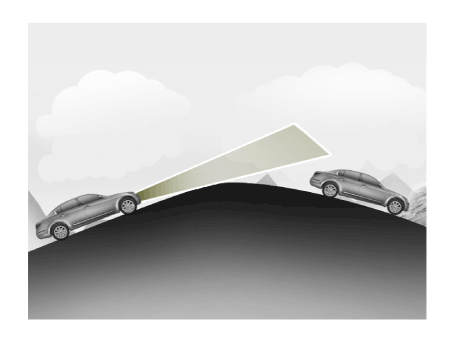
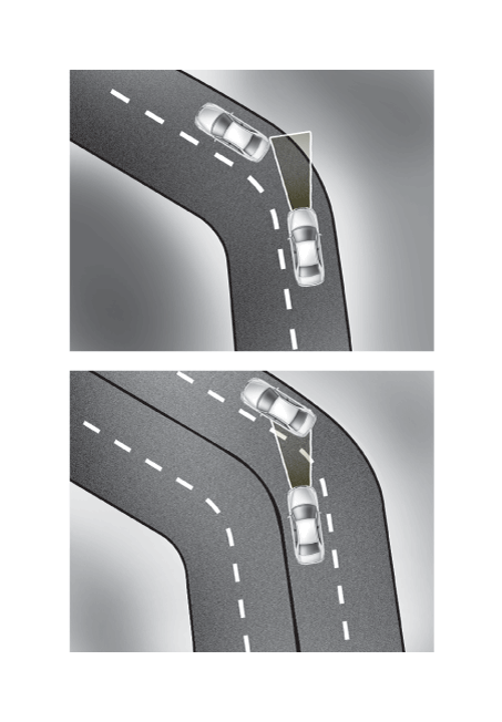
On curves or inclines/declines
|
• |
The smart cruise control system may have limits to detect
distance to the vehicle ahead due to road and traffic
conditions.
|
|
• |
On curves or inclines/declines, the smart cruise control
system may not detect a moving vehicle in your lane,
and then your vehicle may accelerate to the set speed
directly. Also, the vehicle speed may slow down abruptly
when the vehicle ahead is recognized. Select the appropriate
set speed on curves or inclines/declines and control
the vehicle speed by applying the brake pedal if necessary.
|
|
• |
Your vehicle speed can be reduced due to a vehicle in
the adjacent lane. Apply the accelerator pedal and select
the appropriate set speed. Check to be sure that the
road conditions permit.
|
|
|
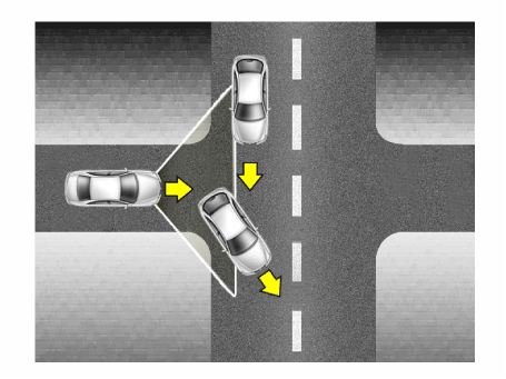
(2) |
Lane changing
|
• |
A vehicle which moves into your lane from an adjacent
lane cannot be recognized by the sensor until it is
in the sensor's detection range.
|
|
• |
Be always cautious because a vehicle which suddenly
moves into your lane can be recognized late by the sensor.
|
|
• |
If the vehicle which moves into your lane is slower
than your vehicle, the speed may decrease to maintain
the distance to the vehicle ahead.
|
|
• |
If the vehicle which moves into your lane is faster
than your vehicle, your vehicle will maintain the selected
speed even the vehicle is in the sensor's detection
range.
|
|
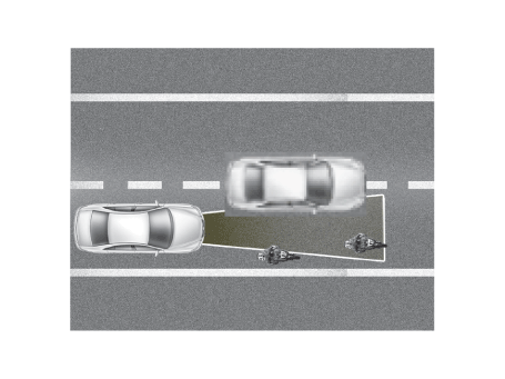
| •
|
Even though a vehicle is in the same lane, a vehicle which is
out of the sensor’s detection range cannot be recognized by
the sensor.
|
| –
|
Small vehicle such as motorcycle, bicycle and cultivator
|
| –
|
A vehicle offset to one side
|
| –
|
A slow-moving vehicle or sudden-decelerating vehicle
|
| –
|
A vehicle with small rear profile such as trailer with no loads
|
|
|
2. |
In this following situation, the front vehicle can’t be recognized correctly
so control the vehicle speed by applying the brake pedal or accelerator
pedal if necessary.
|
(1) |
When the vehicle is pointing upwards due to overloading in the
trunk
|
|
(2) |
While making turns by steering
|
|
(3) |
When driving to one side of the lane
|
|
(4) |
When driving on narrow lanes or on curves
|
|
|
3. |
If the smart cruise control is left on (CRUISE indicator light ON),
the smart cruise control can be switched on accidentally. Keep the smart
cruise control system off (CRUISE indicator light OFF) when the smart
cruise control is not in use, to avoid inadvertently setting a speed.
|
|
4. |
Observe a regulation speed on road when setting the cruise speed.
|
|
5. |
Use the smart cruise control system only when traveling on open highways
in good weather. Do not use the smart cruise control when it may not
be safe to keep the car at a constant speed, for instance, driving in
heavy or varying traffic, or on slippery (rainy, icy or snow-covered)
or winding roads or over 6% up-hill or down-hill roads.
|
|
6. |
Pay particular attention to the driving conditions whenever using the
smart cruise control system.
|
|
7. |
The vehicle cannot be stopped by using the smart cruise control system.
If emergency stop is necessary, you should apply the brakes.
|
|
8. |
Keep the safety distance according to road conditions and vehicle speed.
If the following distance is too close at a high speed driving, it is
dangerous.
|
|
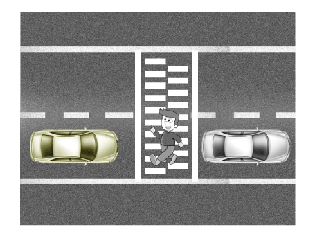
9. |
The smart cruise control system can not recognize a stopped vehicle,
pedestrians or an oncoming vehicle. Always look ahead cautiously to
prevent unexpected and sudden situations from occurring.
|
|
10. |
The smart cruise control system is not a substitute for safe driving
practices but a supplementary function only. It is the responsibility
of the driver to always check the speed and the distance to the vehicle
ahead.
|
|
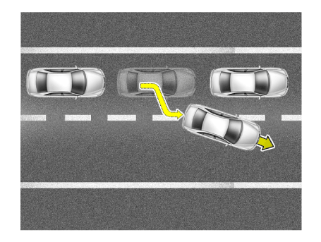
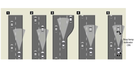
11. |
In front of you, vehicles moving with a frequent lane change may cause
a delay in the system's reaction or may cause the system to react to
a vehicle actually in adjacent lane. Always look ahead cautiously to
prevent unexpected and sudden situations from occurring.
|
|
12. |
Your vehicle may accelerate when a vehicle ahead of you disappears.
When you are warned that the vehicle ahead of you is not detected, drive
with caution.
|
|
13. |
When vehicles are at a standstill and the vehicle in front of you changes
to the next lane, be careful when your vehicle starts to move because
it may not recognize the stopped vehicle in front of you.
|
|
14. |
Always look out for pedestrians when your vehicle is maintaining a distance
with the vehicle ahead.
|
|
15. |
Always be cautious for vehicles with higher height or vehicles carrying
loads that sticks out to the back of the vehicle.
|
Description and operation
| Description and operation |
|
The System may be limited when
| •
|
The radar sensor or camera is blocked with a foreign object
or debris.
|
| •
|
The camera lens is contaminated due to tinted filmed or coated
windshield, damaged glass, or stuck of foreign matter (sticker,
bug, etc.) on the glass.
|
| •
|
Inclement weather such as heavy rain or snow obscures the field
of view of the radar sensor or camera.
|
| •
|
The target in front is too small to be detected.
|
| •
|
The vehicle in front is an oversize vehicle or trailer that
is too big to be detected by the camera recognition system (for
example a tractor trailer, etc.).
|
| •
|
The camera's field of view is not well illuminated (either too
dark or too much reflection or too much backlight that obscures
the field of view)
|
| •
|
The vehicle in front does not have their rear lights ON or their
rear lights are located in an unusual location (modified).
|
| •
|
The windshield glass is fogged up and the clear view of the
road has been obstructed.
|
| •
|
The camera or radar is damaged.
|
|
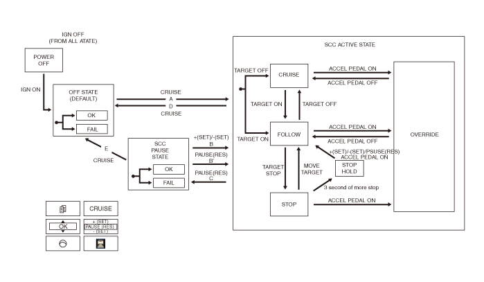
System Flow
| A Type (Front rader none apply) |
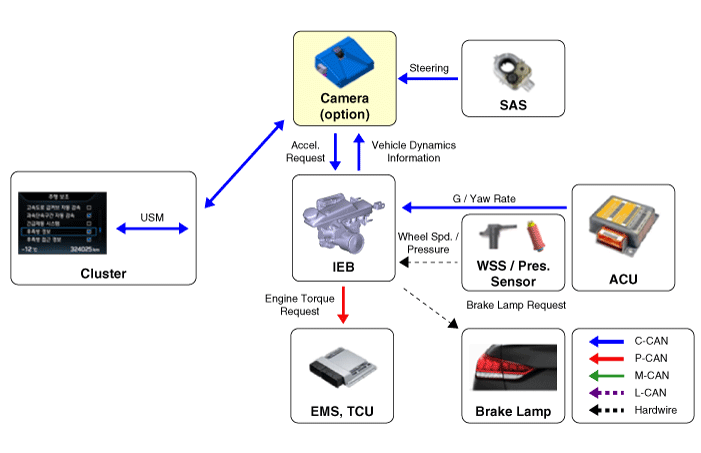
| B Type (Front rader apply) |
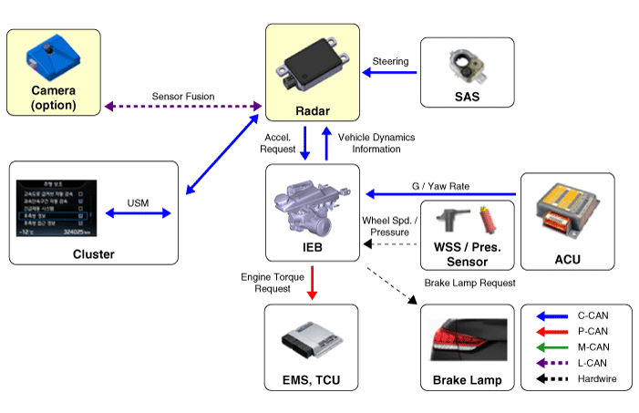
| •
|
Rader, Camera : Detection device (radar and camera) that can
recognize potential obstacles in the front.
|
| •
|
Cluster : Human-Machine Interface (HMI) to warn driver or change
settings.
|
| •
|
ESC : Braking system to automatically brake the car
|
| •
|
Sensors : FCA, contrary to FCA (Smart Cruise Control), has to
work on a stationary car so the system uses the Fusion Target
system to combine radar with camera.
|
|
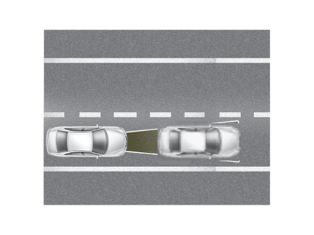
System description
The smart cruise control system allows a driver to program the vehicle to control
the speed and following distance detecting the vehicle ahead without depressing
the brake pedal and the accelerator pedal.
|
1. |
FCA : Forward Collision-avoidance Assist
|
(1) |
FCA system is designed to help avoid a potential collision or
reduce its impact when drivers applies inadequate, delayed or
no brakes at all to avoid a collision.
|
|
(2) |
The system detects the risk factors on the road by using the
frontal impact sensor and warn the driver and activate the emergency
brake to prevent collision or reduce collision speed.
|
|
|
2. |
SCC : Smart Cruise Control
|
(1) |
Cruise speed control : The vehicle maintains the selected speed
if there are not vehicles ahead.
|
|
(2) |
Retardation control : The vehicle decelerates if a vehicle ahead
is detected.
|
|
(3) |
Following distance control : The vehicle maintains the selected
following distance.
|
|
(4) |
Acceleration control : The vehicle accelerates to the selected
speed if a vehicle ahead is not detected.
|
|
System function
|
1. |
Control on curves
|
(1) |
The sensor may not detect a vehicle ahead or may detect a vehicle
on other lanes because the detection range of the sensor is
limited.
|
|
(2) |
On curves, if the vehicle equipped the SCC is driving at high
speed, the vehicle can slip outside. Therefore reduce the speed
on curves even there is not a vehicle ahead. (There is no brake
control by SCC.)
|
|
(3) |
While the vehicle follows a vehicle ahead on straight road,
if the vehicle ahead enters on curve, the vehicle equipped the
SCC may accelerate to follow the vehicle ahead.
|
|
(4) |
On curves, if a vehicle ahead followed is out of range, the
vehicle does not accelerate to the set speed and maintain the
following speed to prevent from accelerating and decelerating
repeatedly. (If the vehicle equipped the SCC changes the lane
or apply the accelerator pedal, the vehicle will accelerate.)
|
|
|
2. |
Warning alarm
If the vehicle equipped the SCC decelerates because a vehicle ahead
decelerates or moves into your lane, the warning will operate.
|
(1) |
In case that the vehicle equipped with SCC is able to decelerate
properly by the system – No warning
|
|
(2) |
In case that the vehicle equipped with SCC is not able to decelerate
properly by the system
|
– |
Indicator in the cluster will blink and the warning
buzzer will sound. (The warning and deceleration by
the system will go on until the brake pedal is applied.)
|
|
|
(3) |
If the vehicle ahead (vehicle speed: less than 30km/h) disappears
to the next lane during following distance control, the warning
chime will sound and a message will appear. Adjust your vehicle
speed for vehicles or objects that can suddenly appear in front
of you.
|
|
|
3. |
Accelerating by driver
Even the vehicle is being decelerated by the SCC system, the vehicle
can be accelerated by applying the accelerator pedal. If the vehicle
is accelerated above the set speed, the indicator in the cluster will
blink.
|
|
4. |
Function of cruise control
|
(1) |
The driver may choose to only use the cruise control mode (speed
control function) by doing as follows:
|
|
(2) |
With the smart cruise control system on (the cruise indicator
light will be on but the system will not be activated), push
the distance to distance switch for more than 2 seconds. "Smart
cruise control (SCC) mode" and "Cruise control (CC) mode" can
be selected.The speed control of the cruise control mode is
the same as that of the smart cruise control mode.
|
|
(3) |
When using the cruise control mode, the driver must manually
access the distance to other vehicles as the system will not
automatically brake to slow down for other vehicles.
|
• When using the cruise control function, your vehicle
may collide with the vehicle ahead when a driver does
not brake properly.
|
|
|
|
5. |
(1) If vehicle speed is high, Highway Curve Zone Auto Slowdown function
will temporarily decelerate your vehicle or limit acceleration to help
you drive safely on a curve based on the curve information from the
navigation.
(2) If vehicle speed is high, Highway Curve Zone Auto Slowdown function
will temporarily decelerate your vehicle or limit acceleration to help
you drive safely on a curve based on the curve information from the
navigation.
|
|
6. |
As a Smart Cruise Control, it prevents collision or slows down collision
speed by alerting drivers and performing emergency braking while driving.
|
|
7. |
Highway Driving Assist (HDA) function
It is a driving convenience system that controls the steering and speed
to keep the safe distance from the vehicle ahead and to prevent lane
departure on highway while Smart Cruise Control is operating.
|
System Operation
FCA : Forward Collision-avoidance Assist)
|
1. |
Basic specification (front camera applied)
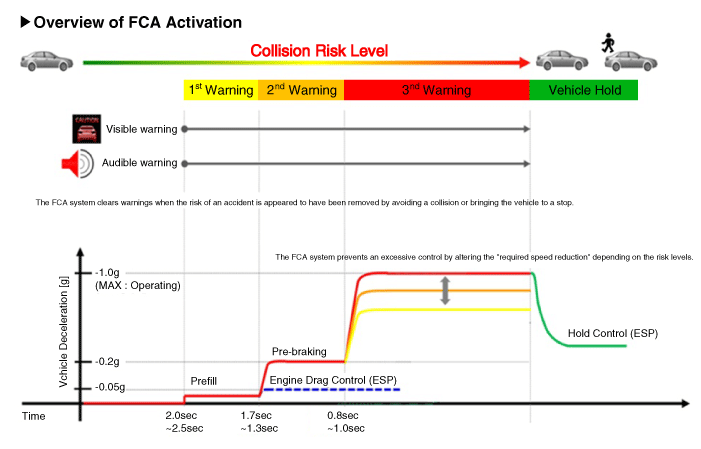
The time indicated will be changed according to vehicle speeds.
| •
|
Step 1 : Issue a visual (display) and vocal alarm when a danger
is detected.
|
| •
|
Step 2 : Reduce engine torque and activates FCA when there is
a high chance of collision.
|
| •
|
Step 3 : Activate emergency brake when a collision is imminent.
|
| •
|
After stopping the vehicle : Maintain the braking control for
a certain time and then release it.
|
|
• |
Braking power is adjusted depending on the risk levels
of collision, but it is released immediately when it
detects the driver's action to avoid a collision.
|
|
1) |
When it exceeded the maximum operation speed.
|
|
2) |
When it detected driver's action to avoid a collision
such as sudden steering changes.
|
|
3) |
When the shift lever is in R or P
|
|
4) |
When you pressed the accelerator pedal half way.
|
|
|
1) |
When you drive at 85km/h - 160km/h or faster, the system
does not go to step 2 of emergency braking.
- Full auto braking is not available.
|
|
2) |
When you drive at 85km/h or faster, the system does
not go to step 3 of emergency braking.
- But a collision may occur at depending on the road
conditions.
- Partial braking may be applied according to the surrounding
environment.
- For the vehicle parked in front, full braking is applied
at level 3 after the warning only when the vehicle speed
is under 75 km/h.
Up to level 2 is performed when the vehicle speed is
over 75 km/h.
- For the pedestrian and cyclists, full braking is applied
at level 3 after the warning only when the vehicle speed
is under 65 km/h.
Up to level 1 is performed when the vehicle speed is
over 65 km/h.
|
|
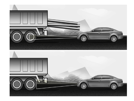
3) |
Offset should be less than 50%.
|
|
4) |
FCA does not work on the vehicles backing up or resisting.
|
|
|
Offset : Rate of non-overlapping on the line between the front
driving car and my car
|
1) |
Offset 0% :
|
|
2) |
Offset 100% :
|
|
|
SCC : Smart Cruise Control
|
1. |
Smart cruise control operating mode.
|
• |
SCC : Smart Cruise Control
|
|
|
|
2. |
Smart cruise control operating conditions.
|
(1) |
Vehicle speed at approximately 0 - 210 km/h
|
|
(2) |
Transmission in D or Sports mode
|
|
(4) |
"CRUISE" switch ON (CRUISE indicator ON)
|
|
|
3. |
Smart cruise control disabling conditions
|
(4) |
Driver’s door opened
|
|
(5) |
Vehicle speed at more than approximately 160km/h (99.4mph)
|
|
(6) |
Vehicle speed at less than approximately 10km/h (5mph)
|
|
(7) |
Transmission in N or P or R
|
|
(8) |
ESP/ TCS / ABS certain period of time operating
|
|
(9) |
An accelerator pedal applied for more than 5min
|
|
(10) |
ESP OFF" switch ON (ESP OFF indicator ON)
|
|
(11) |
Parking brake applied
|
|
(12) |
System failure (The warning indicator ON)
|
|
(13) |
Crack, damage or wrong installation of smart cruise control
unit cover (The warning indicator ON)
|
|
Components and components location
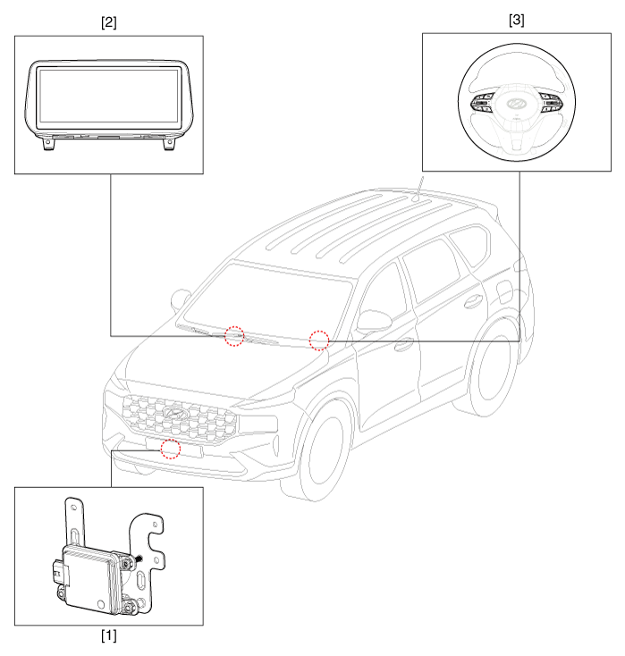
1. Front radar
unit
2. Smart cruise control switch
|
3. AVN Monitor
|
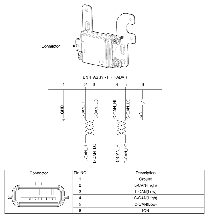
Front Radar Unit. Components and components location
Front Radar Unit. Specifications
Item
|
Specification
|
Power supply (V)
|
12
|
Operation voltage (V)
|
9 - 16
|
Front Radar Unit. Schematic diagrams
Front Radar Unit. Repair procedures
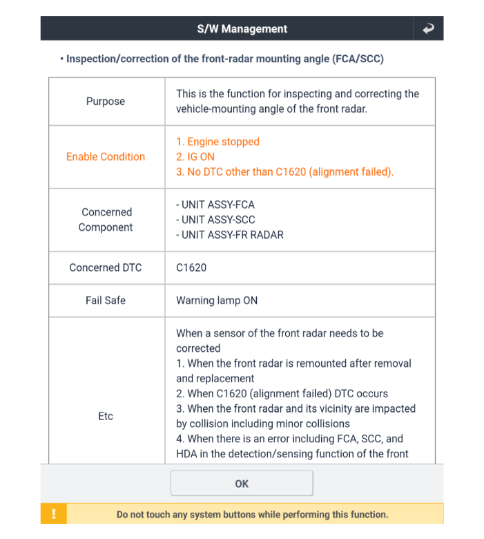
Inspection procedure for vehicle with Forward Collision-Avoidance Assist and
Smart Cruise Control system failure
|
1. |
Check the bumper appearance for accident (check the vehicle appearance
visually and see bumper replacement history).
→ In case of the vehicle was involved in an accident, there is a high
possibility that the FCA radar is out of the original default position.
|
|
2. |
Check for contamination of the radar sensor cover of the bumper.
→If contaminated, there is a high possibility that the FCA system is
deactivated during operation due to the foreign substances.
|
|
3. |
After turning on the engine, check the FAC warning lamp and DTC.
(Refer to the DTC diagnosis guide.)
|
|
1. |
Turn ignition switch OFF and disconnect the negative (-) battery cable.
|
|
2. |
Remove the front bumper.
(Refer to Body - "Front Bumper")
|
|
3. |
Disconnect the front radar connector (A).
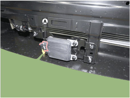
|
|
4. |
Loosen the mounting nuts and remove the front radar (A).
|
Front radar nuts :
9.5 - 10.5 N·m (0.97 - 1.07 kgf·m, 7.0 - 7.7 lb·ft)
|
|
| •
|
Put the vehicle on the level ground.
|
| •
|
Take out heavy luggage from the vehicles’ seats or trunk.
|
| •
|
Set all tires according to the specified pressure.
|
| •
|
Check wheel alignment.
|
| •
|
Check that the front surface of the front radar is clean.
|
|
|
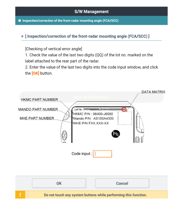
1. |
Check the last 2 digits of Lot. No (A) on label at rear side before
installing the front radar.
|
• |
The meaning of Lot. No (A) is the vertical deviation
angle of front radar inner side.
|
|
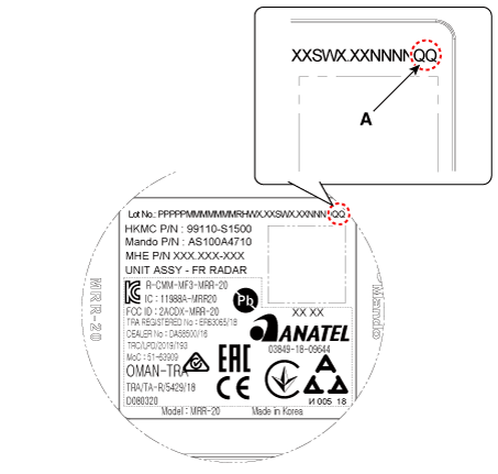
|
|
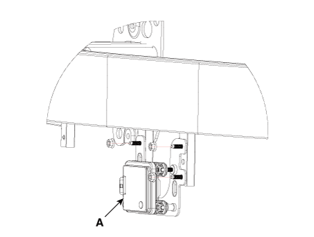
2. |
Install the front radar (A) by tightening the nuts and connect the front
radar connector.
|
Front radar nuts :
9.5 - 10.5 N·m (0.97 - 1.07 kgf·m, 7.0 - 7.7 lb·ft)
|
|
|
3. |
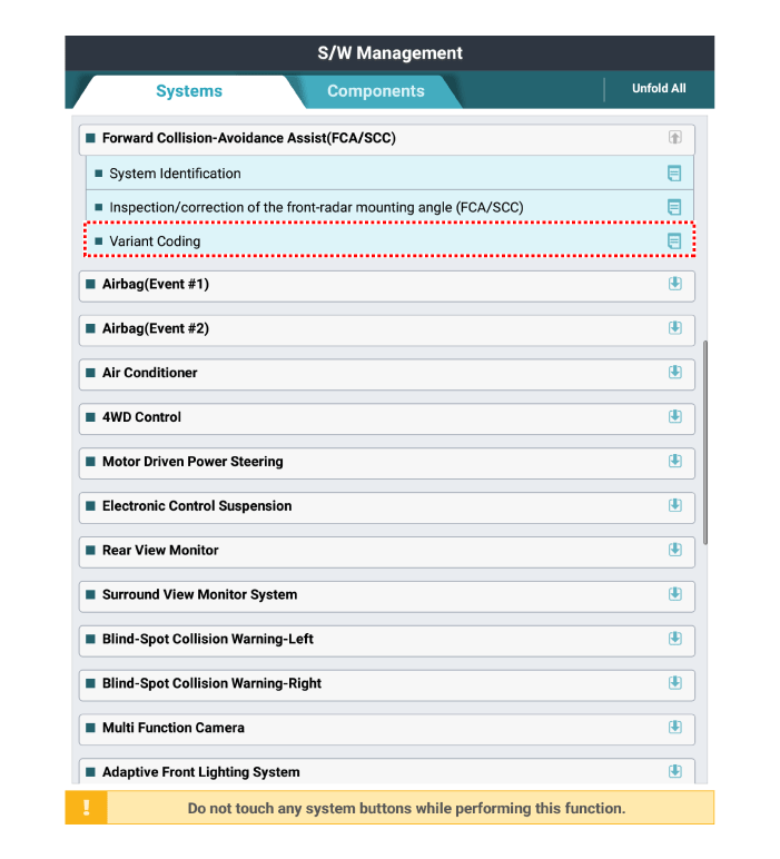
If replaced the front radar with a new one, perform variant coding procedure
by using the diagnostic tool.
|
|
4. |
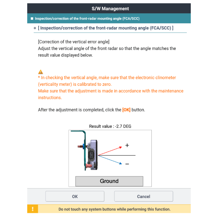
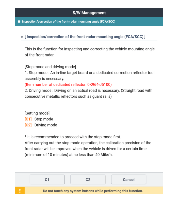
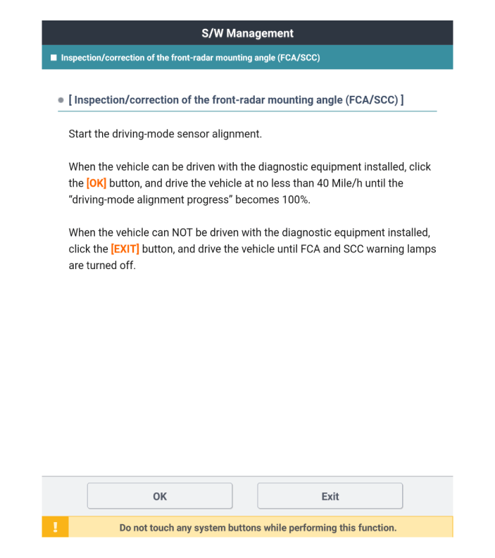
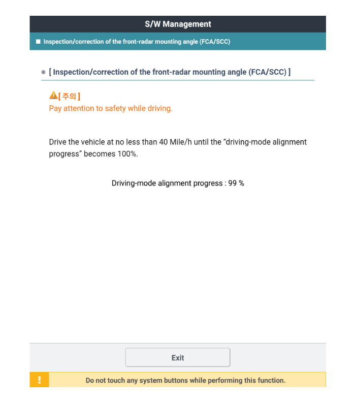
Check and align the front radar mounting angle.
|
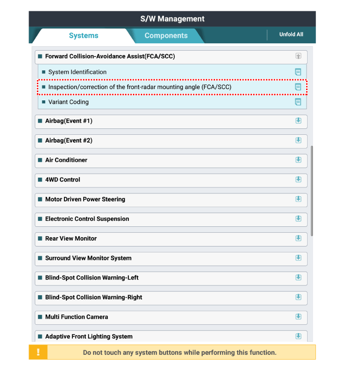
(1) |
Perform the "inspection/correction of the front-radar mounting
angle" using the diagnostic tool.
|
|
(2) |
Input 2 digits of value in the code input box, then press "OK"
|
|
(3) |
Check the vertical angle which is compensated error on diagnostic
tool.
|
• |
The result value is final goal vertical angle
which is compensated inner error of criteria
vertical installation angle -1°.
|
|
|
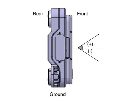
|
(4) |
Check the front radar vertical angle by using the vertical protractor
(tiltmeter).
|
• |
Make sure to perform zero setting before using
vertical protractor. (perform this procedure
periodically)
|
|
• |
Be careful with +/- readings when finding true
vertical using vertical protractor.
|
|
|
|
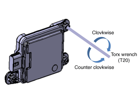
(5) |
Adjust to "target vertical angle" by turning adjusting screw
of front radar.
|
– |
turning clockwise : adjusting (+) angle
|
|
– |
turning counterclockwise : adjusting (-) angle
|
|
• |
There is a chance to be transformed of bracket
if adjusting screw with over strength.
|
|
• |
Must recheck with vertical protractor if vertical
angle is right after adjusting.
|
|
Number of adjustment screw rotation
|
Correction angle
|
Clockwise
|
Counter clockwise
|
0.5
|
+ 0.5°
|
- 0.5°
|
1
|
+ 1.0°
|
- 1.0°
|
1.5
|
+ 1.5°
|
- 1.5°
|
2
|
+ 2.0°
|
- 2.0°
|
2.5
|
+ 2.5°
|
- 2.5°
|
3
|
+ 3.0°
|
- 3.0°
|
3.5
|
+ 3.5°
|
- 3.5°
|
4
|
+ 4.0°
|
- 4.0°
|
4.5
|
+ 4.5°
|
- 4.5°
|
5
|
+ 5.0°
|
- 5.0°
|
|
|
(6) |
Install the front bumper assembly.
(Refer to Body - "Front Bumper Assembly")
|
|
(7) |
Perform the front radar inspection/correction procedure by using
the SST.
(Refer to Smart Cruise Control (Stop & Go) (SCC) Unit-Radar
- "Adjustment")
|
|
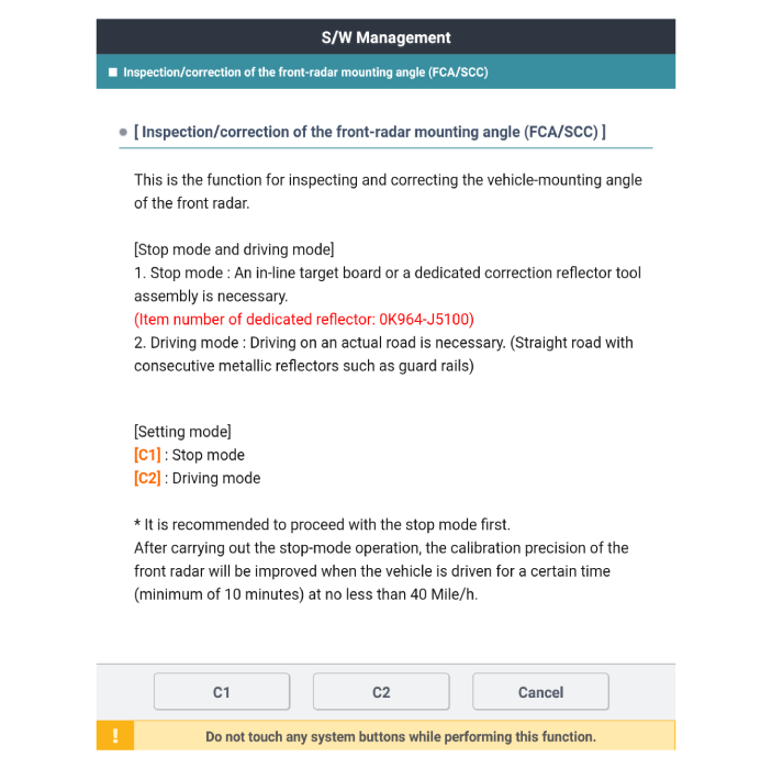
Front Radar Installation Angle Checking / Adjustment Overview
The front radar detects control subject in front, and recognize distance from
the subject, comparing speed and etc. For these reasons the direction of installation
has to be on collinear with vehicle. Therefore, installing angle inspection
and adjustment have to be done in case of the front radar removed and reinstalled
caused by accident or install a new front radar. Accuracy of the front radar
cannot be guaranteed if inspection and adjustment have not been done in case
of mentioned situation before. Front radar inspection/adjustment have to be
done with either stop mode (C1) or drive mode (C2) using by diagnostic tool
Perform adjustment procedure with exclusive adjustment reflector (SST) for stop
mode (C1).
| •
|
after operating stop mode, the accuracy will be increased if
the vehicle has driven more than 10 min.
(drive on straight lane which has metallic reflector.)
|
| •
|
Operate adjustment on real road driving (drive on the road that
has many metallic fixed reflector such as guard rail) for drive
mode. (C2)
|
|
|
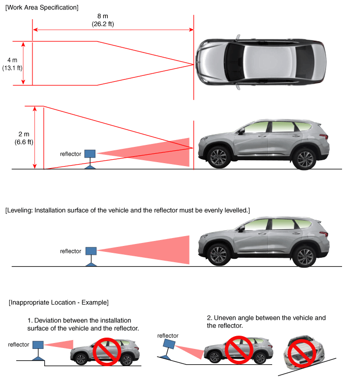
The cases that front radar installation angle checking/adjustment are
needed.
| •
|
Front radar has been replaced
|
| •
|
Front radar has been removed and reinstalled.
|
| •
|
Line up failed DTC has been occurred
|
| •
|
Failure on front radar detecting and cognition function
|
| –
|
failed to detect vehicle in front while functioning
|
| –
|
often detecting error of side lane
|
| –
|
often detecting error even though any object is not in front
|
|
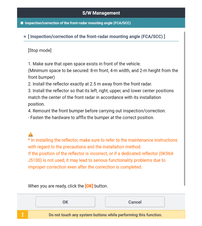
How to Check / Adjust Front Radar Installation Angle - Stop Mode
|
Preparation before the front radar alignment :
| •
|
Put the vehicle on the level ground.
|
| •
|
Take out heavy luggage from the vehicles’ seats or trunk.
|
| •
|
Set all tires according to the specified pressure.
|
| •
|
Check wheel alignment.
|
| •
|
Check that the front surface of the front radar is clean.
|
|
| •
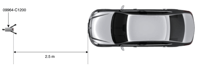
|
Perform in an area with minimum clearance of 8m (26.2 ft) front,
4m (13.1 ft) sides, and 2 m (6.6 ft) above the vehicle.
|
| •
|
Install the reflector exactly 2.5 m (8.2 ft) away from the Front
Radar.
|
| •
|
The reflector has to be installed at same place (height and
angle) as front radar center.
(If height and angle are different, then adjustment can not
be done correctly.)
|
| •
|
Remove objects (metal plates, resins, etc.) that may cause electric
signal interference from the area where front radar alignment
is performed.
|
| •
|
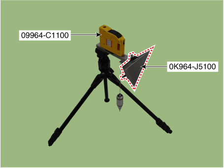
Make sure to use exclusive reflector (OK964-J5100)
|
| •
|
Be sure that the vehicle is not moved and free from vibration
when performing front radar alignment
(getting in/out or opening/closing doors).
|
| •
|
IG has to be on when performing front radar alignment. (engine
stop condition)
|
|
|
1. |
Stop the vehicle horizontally at a flat place.
|
|
2. |
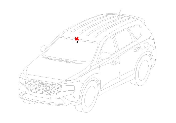
Mark the center point (B) after measuring the distance on top of wind
glass.
|
|
3. |
Mark the center point of emblem (A).
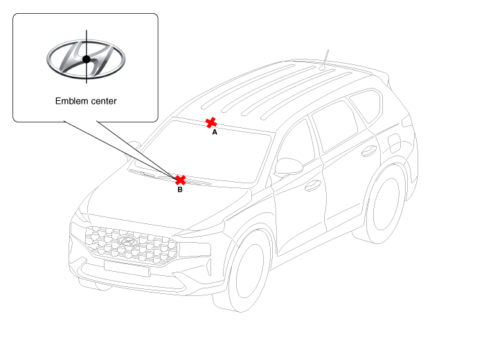
|
|
4. |
Install the laser (09964-C1200) to the tripod (09964-C1300).
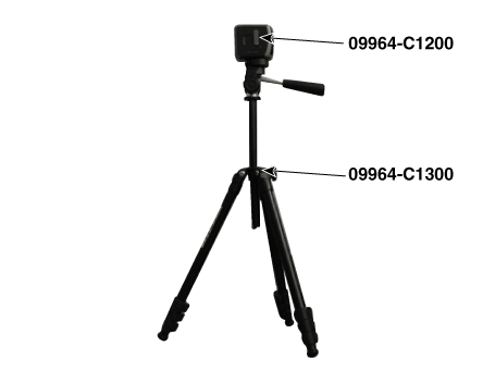
|
|
5. |
Place the laser (09964-C1200) at 2.5m (8.2 ft) to the front of the vehicle.
|
|
6. |
Match the vertical line of laser to (A) and (B) using the laser (09964-C1200).
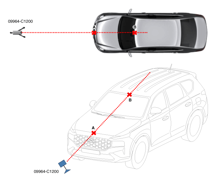
|
|
7. |
Mark (C) at 2.5 m (8.2 ft) from (A) in front of the vehicle.
|
|
8. |
Mark (D) at the place which is 13mm away from (C) to the right in vertical
direction.
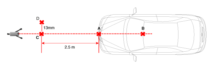
|
|
9. |
Remove the laser (09964-C1200) from the tripod (09964-C1300).
|
|
10. |
Mount the reflector (09964-C1100) onto the tripod (09964-C1300).
|
|
11. |
Mount the reflector adapter (0K964-J5100) to the reflector (09964-C1100).
|
|
12. |
Set the reflector horizontal using the leveler (A) which is built in
the tripod (09964-C1300).
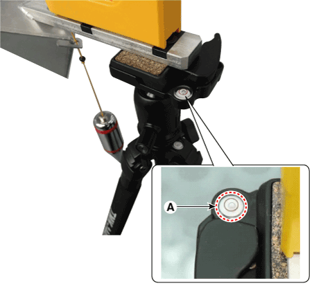
|
|
13. |
Align the vertical weight (A) of the reflector (09964-C1100) with the
point (D).
|
|
14. |
Set the height of the reflector adapter (0K964-J5100) to 375 mm (14.76
inch).
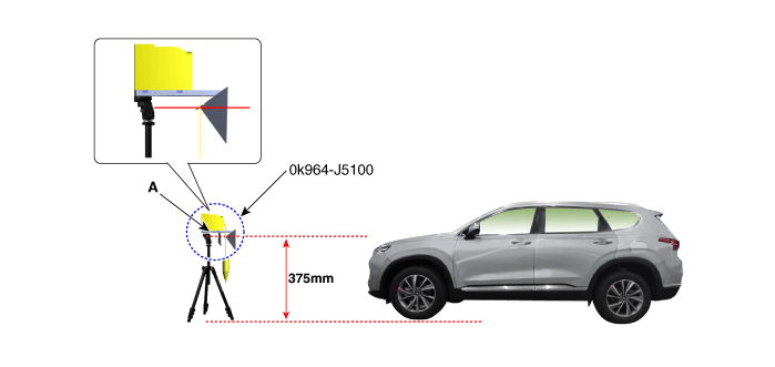
|
|
15. |
Remove the vertical weight from the reflector (09964-C1100).
|
• |
It can be effected to adjustment if the vertical weight
is still left.
|
|
|
|
16. |
Check again the front radar and the surface of front bumper for the
following items with the eyes.
|
• |
Make sure that there is no debris, or reflecting object
on the surface of the radar.
|
|
• |
Make sure that there is no debris, or reflecting object
on the radiator grill.
|
|
|
|
17. |
Select C1 (stop mode) to inspect and adjust the front radar installation
angle by following procedure on diagnostic tool screen.
|
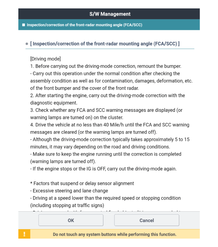
How to Check / Adjust Front Radar Installation Angle - Drive Mode
| •
|
After operating stop mode, the accuracy will be increased if
the vehicle has driven more than 10 min.
(drive on straight lane which has metallic reflector.)
|
|
If stop mode operation can not be done, then use drive mode to proceed front
radar adjusting procedure.
|
Preparation before the front radar alignment :
| •
|
Put the vehicle on the level ground.
|
| •
|
Take out heavy luggage from the vehicles’ seats or trunk.
|
| •
|
Set all tires according to the specified pressure.
|
| •
|
Check wheel alignment.
|
| •
|
Check that the front surface of the front radar is clean.
|
|
|
1. |
Select C2 (drive mode) to inspect and adjust the front radar installation
angle by following procedure on diagnostic tool screen.
|
|
2. |
In case of front radar inspection/correction failure, check the inspection/correction
conditions.
|
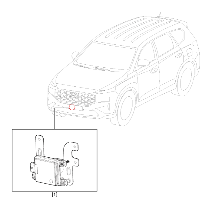
Smart Cruise Control (SCC) Switch. Components and components location
1. Front radar
unit
2. AVN Monitor
|
3. Smart cruise
control switch
|
Smart Cruise Control (SCC) Switch. Schematic diagrams
[Trip/Cruise/Smart Cruise]
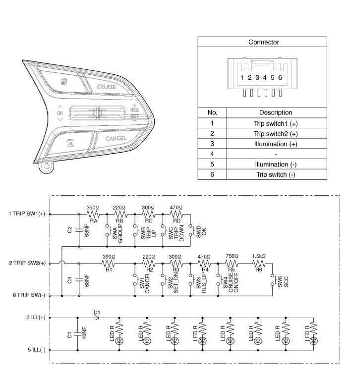
Smart Cruise Control (SCC) Switch. Repair procedures
|
1. |
Check for resistance between terminals in left switch position.
[Audio/Bluetooth]
Switch
|
Connector terminal
|
Resistance (± 3%)
|
SEEK Up
|
1 - 6
|
430 Ω
|
SEEK Down
|
1 - 6
|
1.1 kΩ
|
MODE
|
1 - 6
|
2.11 kΩ
|
MUTE
|
1 - 6
|
3.11 kΩ
|
Volume up
|
1 - 6
|
4.61 kΩ
|
Volume down
|
1 - 6
|
6.81 kΩ
|
Voice
|
1 - 6
|
10.71 kΩ
|
END
|
1 - 6
|
18.91 kΩ
|
SEND
|
1 - 6
|
40.91 kΩ
|
|
|
2. |
Check for resistance between terminals in right switch position.
[Trip/Cruise]
Switch
|
Connector terminal
|
Resistance (± 3%)
|
CANCEL
|
2 - 6
|
390 Ω
|
SET (-)
|
2 - 6
|
610 Ω
|
RES (+)
|
2 - 6
|
910 Ω
|
Cruise ON/OFF
|
2 - 6
|
1.38 kΩ
|
Cruise Mode
|
2 - 6
|
2.13 kΩ
|
Smart Cruise
|
2 - 6
|
3.63 kΩ
|
Trip Group
|
1 - 6
|
390 Ω
|
Trip Up
|
1 - 6
|
610 Ω
|
Trip Down
|
1 - 6
|
910 kΩ
|
Trip OK
|
1 - 6
|
1.38 kΩ
|
|
|
1. |
Disconnect the negative (-) battery terminal.
|
|
2. |
Remove the driver airbag module.
(Refer to Restraint - "Driver Airbag (DAB) Module and Clock Spring")
|
|
3. |
Remove the steering wheel.
(Refer to Steering System - "Steering Column and Shaft")
|
|
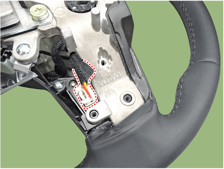
4. |
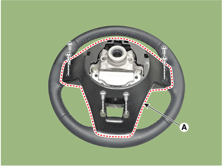
Remove the steering wheel cover (A) after loosening the screws.
|
|
5. |
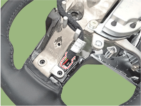
Loosen the screws and then disconnect the steering wheel remote control
switch connector.
|
|
6. |
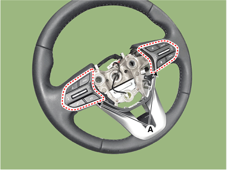
Remove the remote control switchs (A).
|
|
1. |
Install the remote control switch on the steering wheel.
|
|
2. |
Install the steering wheel.
|
|
3. |
Reconnect the remote control switch connector and airbag connectors.
|
Make sure that the switch connector is plugged in properly.
|
|
|
4. |
Install the driver airbag module.
|
|
5. |
Connect the negative (-) battery terminal.
|
Description and operation Description and Operation Blcok Diagram • This system monitors the driving situations through the radar and the camera. Thus, for a situation out of the sensing ...
Description and operation Description Rear Corner Radar is a system that measures the relative speed and distance from the following vehicles by using two electromagnetic wave radar sensors attached to ...
 Hyundai Santa Fe (TM): Front Radar System


 Front View Camera System
 Rear Corner Radar System