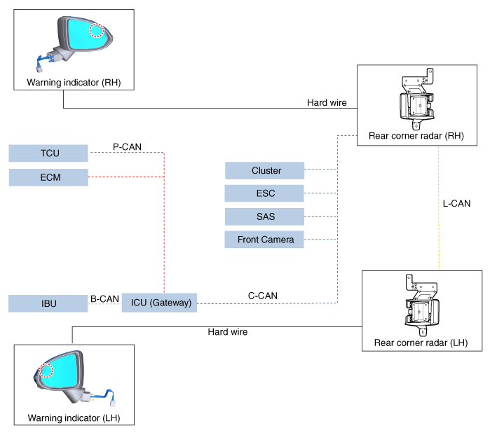
 Hyundai Santa Fe (TM): Rear Corner Radar System
Description and operation
| Description |
| • |
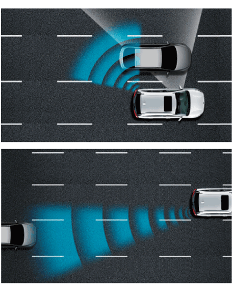
Blind-Spot Collision Warning (BCW)
Audible warning and signal on the mirror when sensing a vehicle in the
blind spot area or when the vehicle is approaching at a high speed.
|
| • |
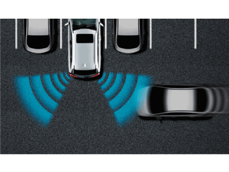
Rear Cross-Traffic Collision-Avoidance Assist (RCCA)
Warns the driver when it senses a vehicle approaching from the rear
outer range while vehicle is in reverse (R) position.
Collision avoidance assistance applies the brakes in the event of a
collision risk.
|
| • |
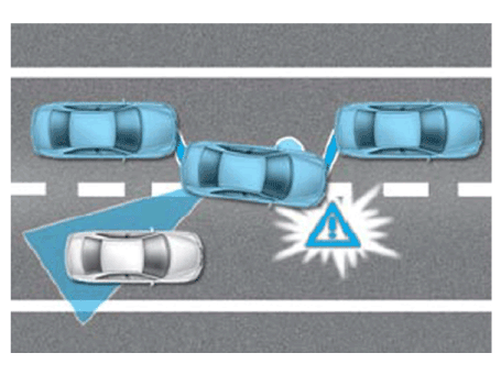
BCA(Blind-Spot Collision-Avoidance Assist) : When the lane departure,
BCA generates avoidance for another vehicle within the blind spot zone.
|
| • |
SEA (Safe Exit Assist) : When getting off the vehicle, SEA generates
alarm to alert another vehicle approaching from the rear.
|
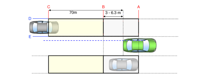
| Blind-Spot Collision Warning (BCW) |
| 1. |
Conditions for BCW warning ON
â‘ The entire body of the target vehicle is located behind the line A.
② Any part of the target vehicle pass the line B.
③ Any part of the target vehicle passes the line D and Hysteresis In.
â‘Ł The entire part of the target vehicle passes the line E and Hysteresis
In.
|
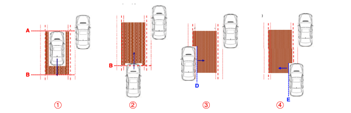
| 2. |
Conditions for BCW warning OFF
â‘ The entire body of the target vehicle moves before the line A.
② The entire body of the target vehicle moves behind the line B.
③ The entire body of the target vehicle passes the line D and Hysteresis
Out.
â‘Ł The entire part of the target vehicle passes the line E and Hysteresis
Out.
|
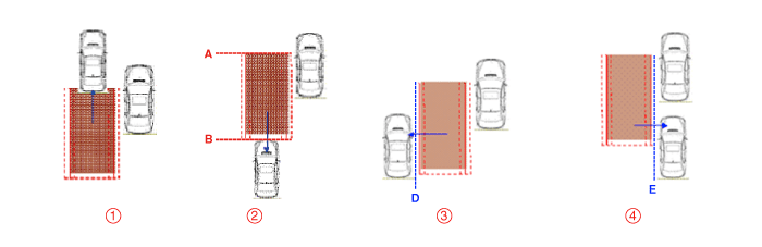
| 3. |
Conditions for LCA warning ON
â‘ The entire body of the target vehicle is located behind the line B.
② Any part of the target vehicle pass the line C.
③ Any part of the target vehicle passes the line D and Hysteresis In.
â‘Ł The entire part of the target vehicle passes the line E and Hysteresis
In.
⑤ In the all above condition, TTC(Time to Collision) is not less than
4.5 sec.
|
| 4. |
Conditions for LCA warning OFF
â‘ The entire body of the target vehicle is located before the line B.
② The entire body of the target vehicle pass the line C.
③ The entire body of the target vehicle passes the line D and Hysteresis
Out.
â‘Ł The entire body of the target vehicle passes the line E and Hysteresis
Out.
⑤ In the all above condition, TTC(Time to Collision) is more than 4.5
sec.
|
| 5. |
Sensor activation conditions
â‘ BCW & LCA switch (indicated by the switch LED) is on.
② Vehicle Speed: 30 km/h or faster
③ Curvature radius: 100m or more
â‘Ł Relative car speed: -10 - 255km/h
("-" means overtaking the preceding vehicle)
|
| 6. |
Sensor deactivation conditions
â‘ BCW & LCA switch (indicated by the switch LED) is off.
② Vehicle Speed: 27 km/h or slower
③ Curvature radius: 70m or less
â‘Ł Relative car speed: All except -10 - 255km/h
("-" means overtaking the preceding vehicle)
|
| 7. |
System control prohibition
â‘ The radar is covered by debris: System conditions - Blockage message
is outputted
② The radar installation is damaged by an outside shock: Send the error
code
③ BCW & LCA system fails: Send the error code
â‘Ł The radar is overheated: System conditions - Over Temperature message
is outputted.
|

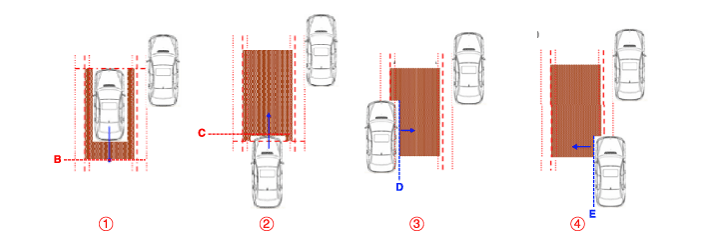
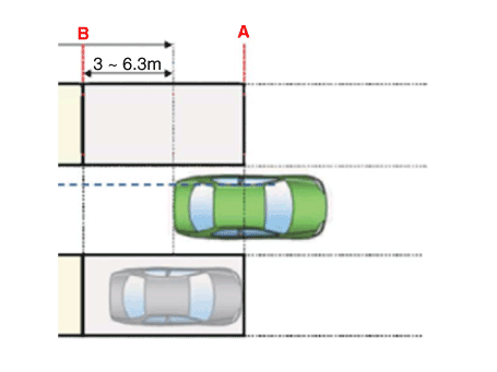
| 8. |
BCA-R (Blind-Spot Collision-Avoidance Assist System - Rear)
|
| 9. |
BCW activation condition
|
| 10. |
Warning zone
A to B : Blind spot zone
B to C : Closing vehicle zone
|
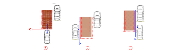
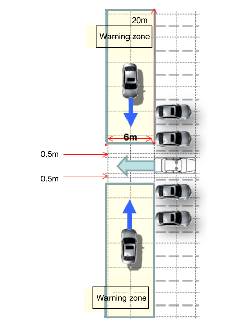
| Rear Cross-Traffic Collision Warning System (RCCW) |
| 1. |
Rear Cross-Traffic Collision Warning System (RCCW) activation condition
â‘ Generates warning in case of collision risk with the vehicle approaching
from left and right side of your vehicle while reversing out of the
parking space.
② Based on the Time To Collision (TTC), the warning is generated for
the vehicle that is possible to collide within 3.5 seconds.
③ Warning zone is as follows:
|
| Blind-Spot Collision-Avoidance Assist System (BCA) |
| 1. |
Blind-Spot Collision-Avoidance Assist System (BCA ) activation condition
|
Components and components location
| Components |
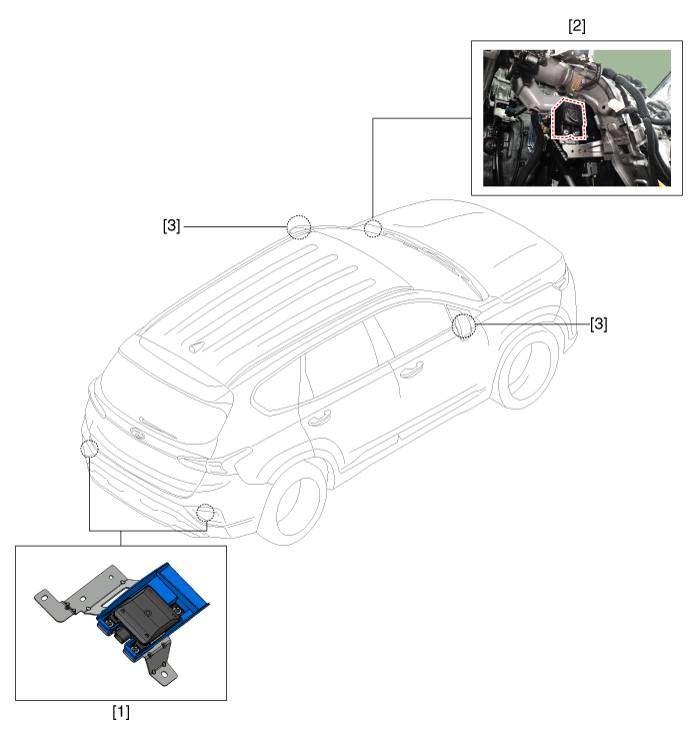
| 1. Rear corner
radar unit 2. Speaker (Cluster) |
3. Warning indicator |
Troubleshooting
| 1. |
In the body electrical system, failure can be quickly diagnosed by using
the vehicle diagnostic system (Diagnostic tool).
The diagnostic system (Diagnostic tool) provides the following information.
|
| 2. |
Connect the cable of Diagnostic tool to the data link connector in driver
side crash pad lower panel, and turn on the Diagnostic tool.
|
| 3. |
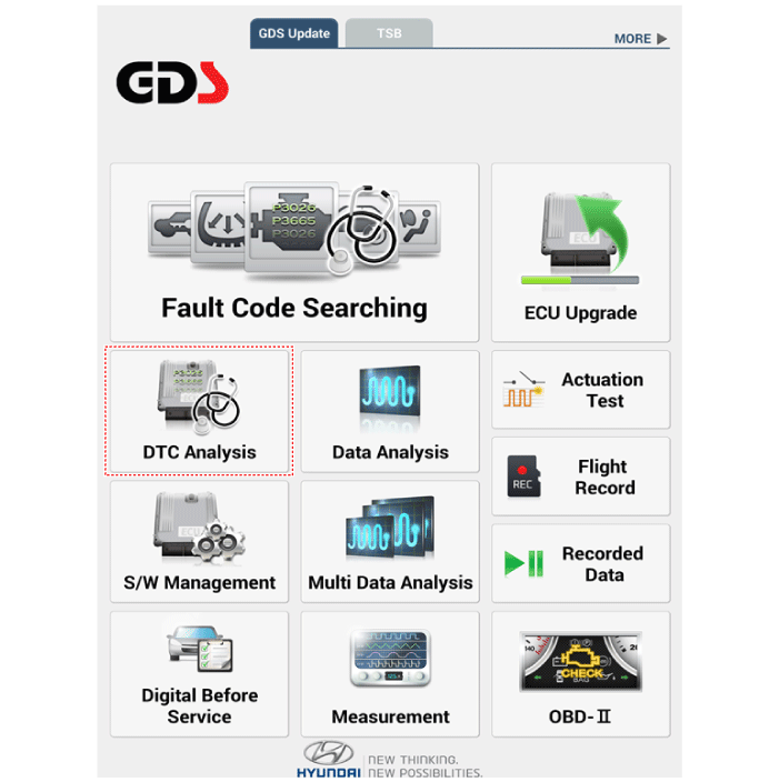
If diagnose the vehicle by Diagnostic tool, select "DTC Analysis" and
"Vehicle".
|
| 4. |
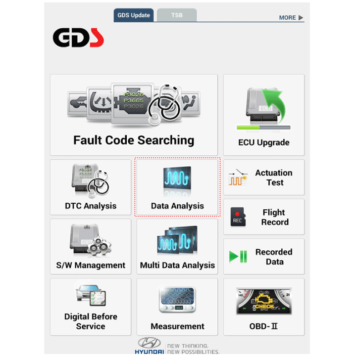
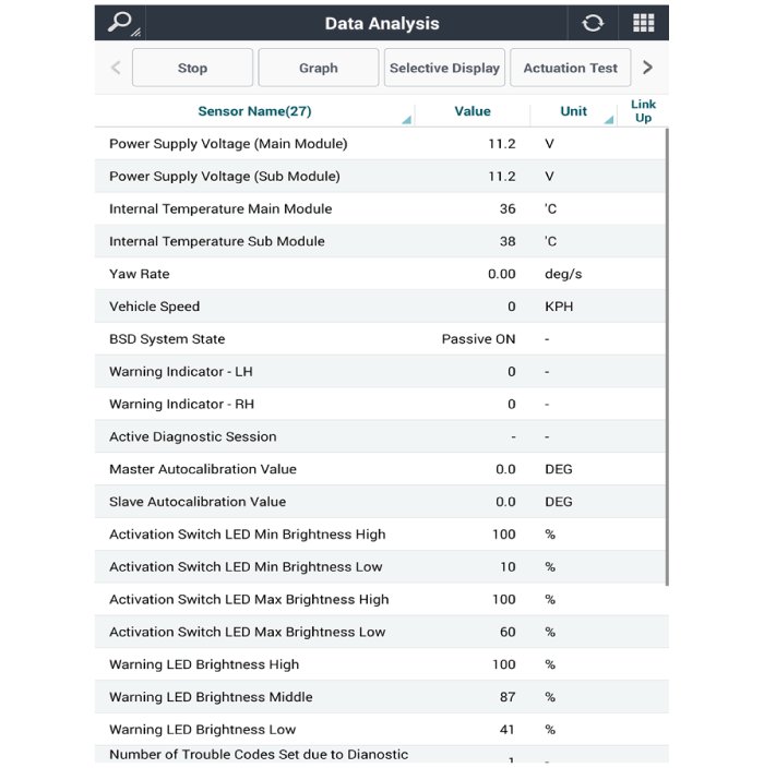
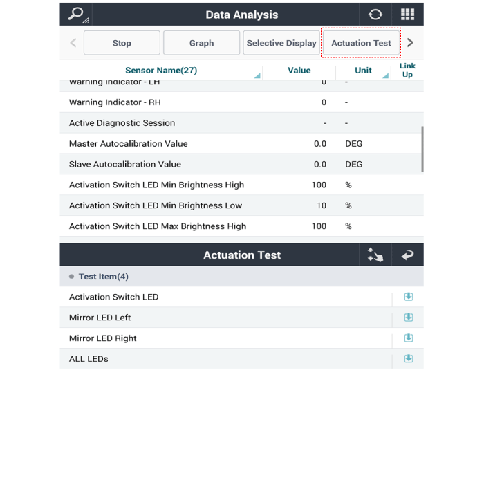
If check current status, select the "Data Analysis" .
|
| 5. |
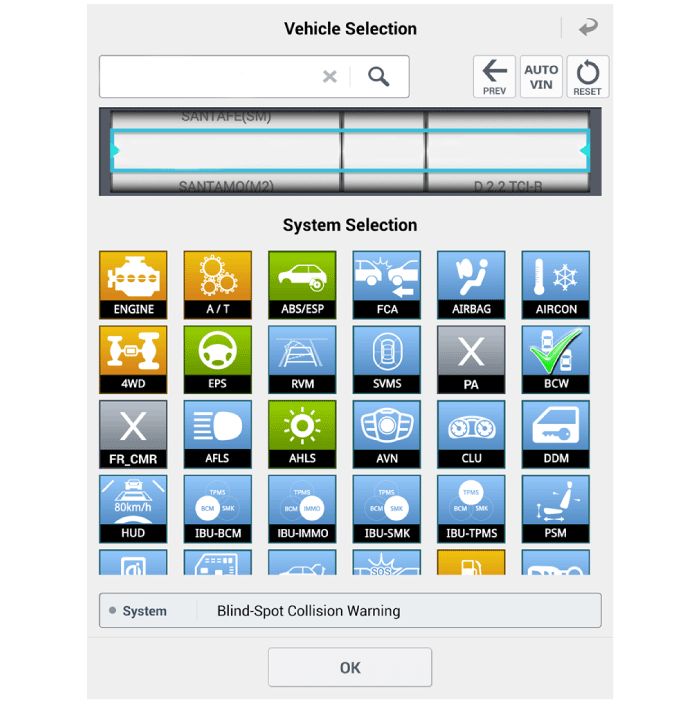
Select "BCW", if you want to check current data of BCW system.
|
| 6. |
If you want to check each module operation forcefully, select "Actuation
test".
|
Rear Corner Radar Unit. Specifications
| Specifications |
| [BCW, BCA] |
|
Items |
Blind-Spot Collision Warning (BCW) |
Blind-Spot Collision- Avoidance Assist (BCA) |
Blind-Spot Collision- Avoidance Assist (BCA) |
|
※Parallel Exit |
|||
|
Rated voltage |
DC 12V |
||
|
Operating voltage |
9V ~ 16V |
||
|
Operating speed |
20 ㎞/h ~ 255 ㎞/h |
60 ㎞/h ~ 200 ㎞/h |
0 ㎞/h ~ 3 ㎞/h |
|
Sensible distance |
70m |
80m |
|
|
Frequency |
24 GHz |
||
|
Numbers |
2 EA |
||
| [RCCW, RCCA] |
|
Items |
Rear Cross-Traffic Collision Warning System (RCCW) |
Rear Cross-Traffic Collision- Avoidance Assist (RCCA) |
|
Rated voltage |
DC 12V |
|
|
Operating voltage |
9V ~ 16V |
|
|
Operating speed |
0 km/h ~ 10 km/h |
0.1 km/h ~ 10 km/h |
|
Sensible distance |
25m |
|
|
Curvature radius |
- |
|
|
Frequency |
24 GHz |
|
|
Numbers |
2 EA |
|
| [SEA] |
|
Items |
Safe Exit Assist (SEA) |
|
Rated voltage |
DC 12V |
|
Operating voltage |
9V ~ 16V |
|
Operating speed |
0 km/h ~ 3 km/h |
|
Sensible distance |
30m |
|
Curvature radius |
- |
|
Frequency |
24 GHz |
|
Numbers |
2 EA |
Rear Corner Radar Unit. Schematic diagrams
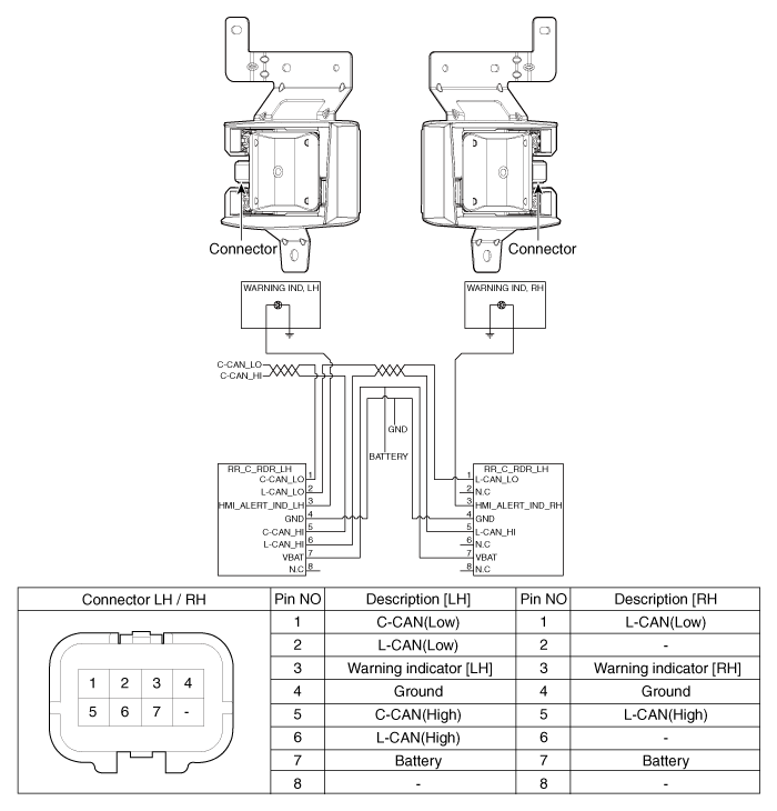
| Connector and Terminal Function |
Rear Corner Radar Unit. Repair procedures
| Removal |
| 1. |
Disconnect the negative (-) battery terminal.
|
| 2. |
Remove the rear bumper cover.
(Refer to Body - "Rear Bumper Cover")
|
| 3. |
Disconnect the rear corner radar connector (A).
|
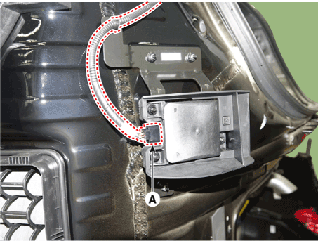
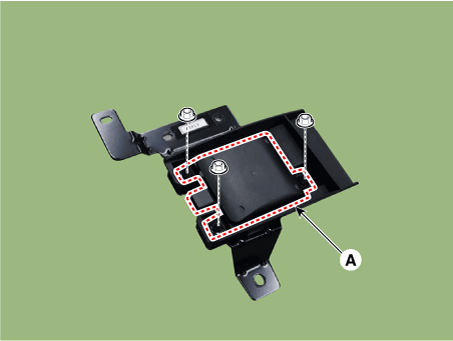
| 4. |
Loosen the mounting nuts and remove the rear corner radar unit (A)
|

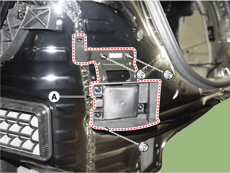
| 5. |
When replacing the bracket, push the unit (A) in the direction of the
arrow to remove the bracket.
|
| Installation |
| 1. |
Install the rear corner radar unit and bracket.
|
| 2. |
install the rear bumper cover.
|
| 3. |
Connect the negative (-) battery terminal.
|
| 4. |
Perform "Correcting the Rear Corner Radar Unit Angle" procedures.
|
| 5. |
Perform "Rear Corner Radar Calibration" procedures.
|
Warning Indicator. Components and components location
| Components |
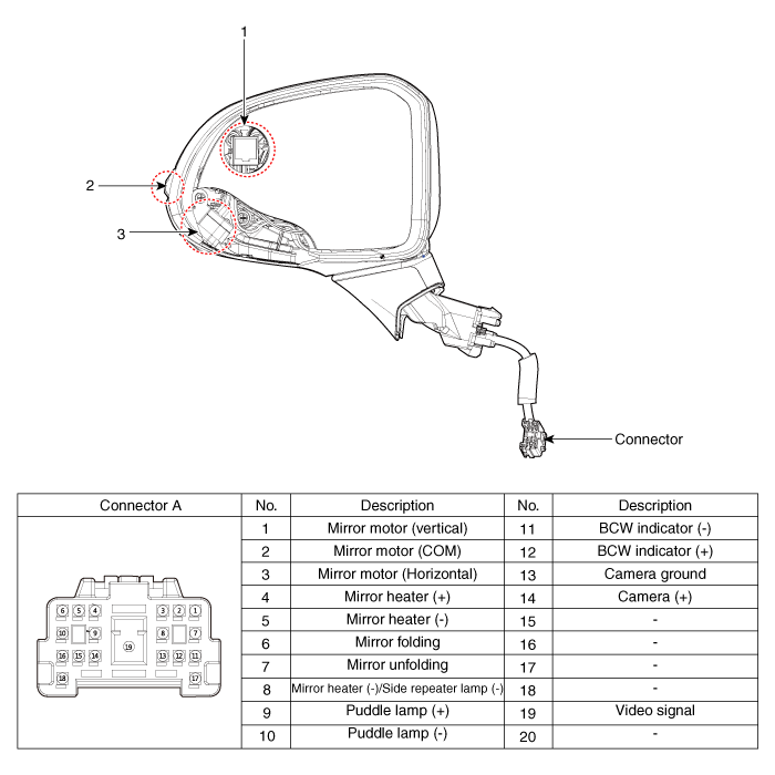
| 1. BCW Indicator 2. Side repeater lamp |
3. SVM Camera |
Warning Indicator. Repair procedures
| Inspection |
| 1. |
Disconnect the negative (-) battery terminal.
|
| 2. |
Remove the front door trim.
(Refer to Body - "Front door trim")
|
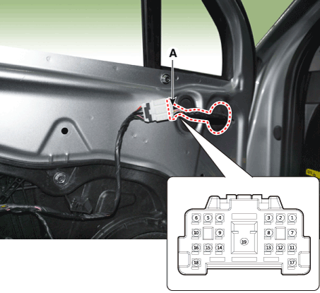
| 3. |
Disconnect the power door mirror connector from the harness
BCW indicator
|
| Removal |
| 1. |
Disconnect the negative (-) battery terminal.
|
| 2. |
Remove the door mirror assembly.
(Refer to Body - "Outside Rear View Mirror")
|
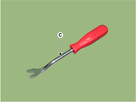
| 3. |
Using a fastener remover (C), remove the mirror (A) as illustration
below.
|
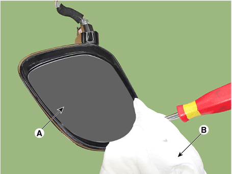

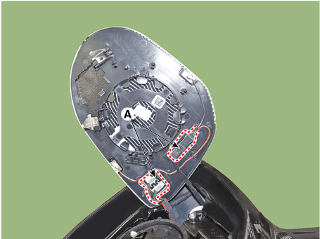
| 4. |
Disconnect heat wire and BCW connectors (A) and then remove the mirror.
|
| Installation |
| 1. |
Connect mirror heat wire connector and BCW connector then mount mirror.
|
| 2. |
Install the door mirror assembly.
|
| 3. |
Connect (-) battery terminal then check if door mirror lamp works normally.
|
 Front Radar System
General safety information and caution General Safety Information and Caution 1. Be careful when driving the vehicle using the smart cruise control system as follows. (1) On curves or inclines/declines ...
 Parking Distance Warning (PDW)
Description and operation Description • PDW consists of 8 sensors (front : 4 units, rear : 4 units) that are used to detect obstacles and transmit the result in three separate warning levels, the first, ...
See also:
Interior features
Cup holder Cups or small beverages cups may be placed in the cup holders. WARNING Avoid abrupt starting and braking when the cup holder is in use to prevent spilling your drink. If hot liquid spills, you ...
EBD(Electronic Brake-force Distribution). Description and Operation
Operation The EBD system (Electronic Brake force Distribution) as a sub-system of the ABS system is to control the maximum braking effectiveness by the rear wheels. It further utilizes the efficiency of ...
One person per belt
Two people (including children) should never attempt to use a single seat belt. This could increase the severity of injuries in case of an accident. ...
