 Hyundai Santa Fe (TM): Keyless Entry And Burglar Alarm
Description and operation
| Description |
Burglar Alarm State [B/A State]
|
B/A State |
Description |
||||||
|
DISARM |
|
||||||
|
ARMWAIT |
|
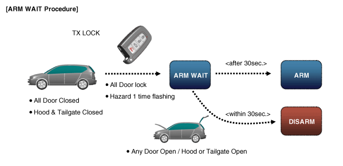
※ Remark: On Smart key system, it works the same way with passive lock
|
B/A State |
Description |
||||||
|
AUTO LOCK TIMER 1 |
|
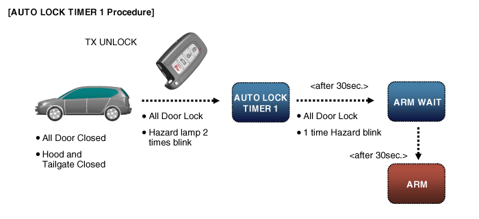
※ Remark: On Smart key system, it works the same way with passive unlock
|
B/A State |
Description |
||||||||
|
AUTO LOCK TIMER 2 |
|
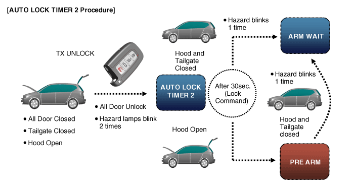
※ Remark: On Smart key system, it works the same way with passive unlock
|
B/A State |
Description |
||||||||||||
|
PRE ARM |
|
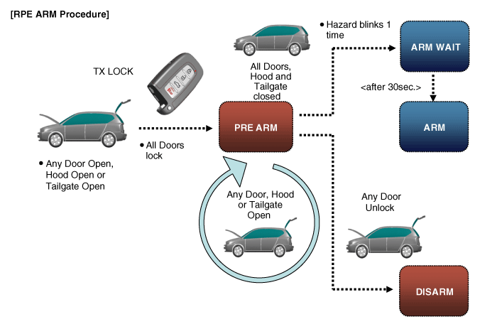
|
B/A State |
Description |
||||||
|
RE ARM |
|
|
B/A State |
Description |
||||||||||
|
AUTOLOCK TIMER3 |
|
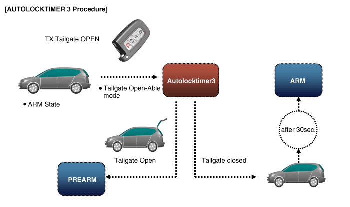
Components and components location
| Component Location |
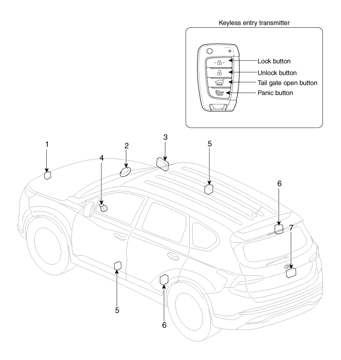
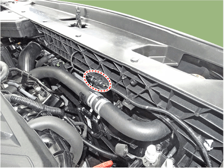
| 1. Hood switch 2. Burglar horn 3. Intergrated Body Control Unit (IBU) 4. Key warning switch |
5. Front door
lock actuator & switch 6. Rear door lock actuator & switch 7. Tailgate open switch |
Specifications
| Specification |
|
Item |
Specification |
|
Power source |
3V |
|
Operating temperature |
-20°C to +60°C (-4°F to- +140°F) |
|
RF Modulation |
FSK |
|
LF Modulation |
ASK |
|
RF frequency |
433.92MHz |
|
Battery |
CR2032 |
|
Transmissible distance |
10m or more |
|
Life of battery |
2years or more (at 20 times per day) |
|
Button number |
4 |
|
Function |
Door lock |
|
Door unlock |
|
|
Tailgate unlock |
|
|
Panic |
Repair procedures
| Inspection |
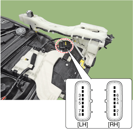
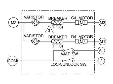
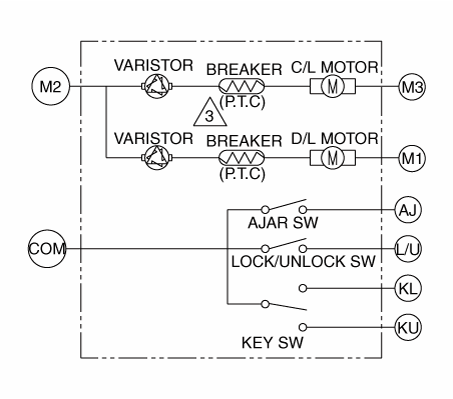
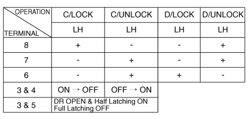
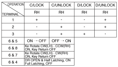
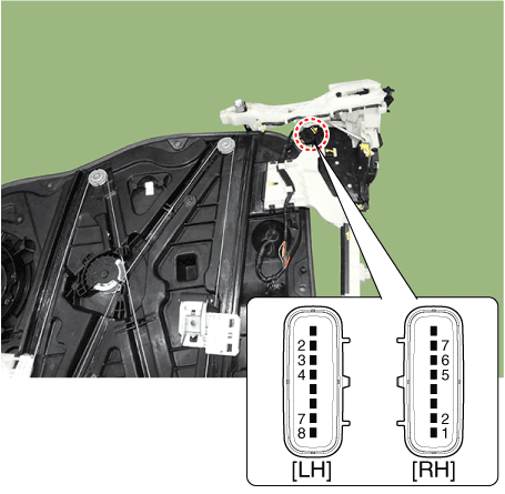
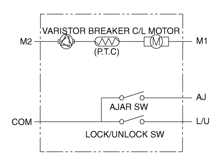
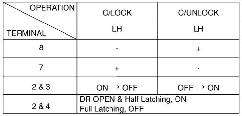
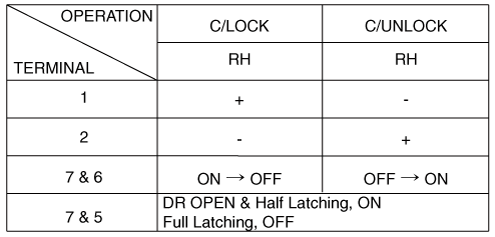
Front Door Lock Module Inspection
| 1. |
Remove the front door trim.
(Refer to Body - "Front Door Trim")
|
| 2. |
Remove the front door module.
(Refer to Body - "Front Door Module")
|
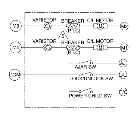
| 3. |
Disconnect the connectors from the actuator.
|
| 4. |
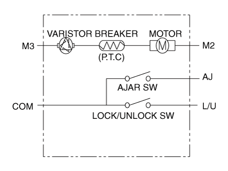
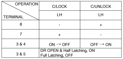
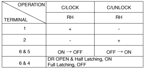
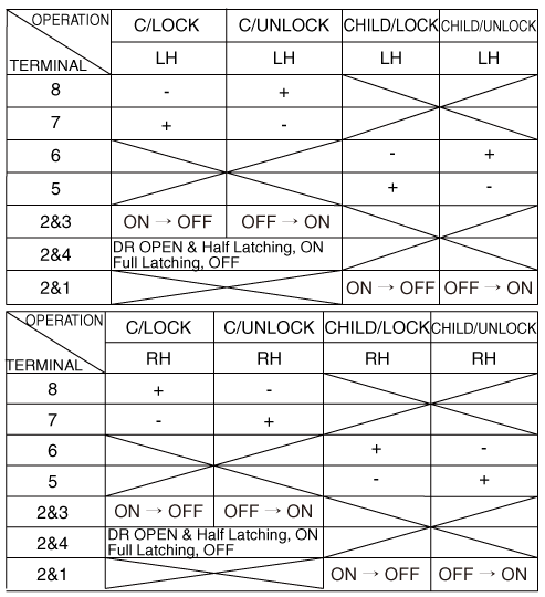
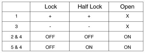
Check actuator operation by connecting power and ground according to
the table.
[Dead Lock]
[Central Lock]
[Central Lock]
[Dead Lock]
Driver
Passenger
|
Rear Door Lock Module Inspection
| 1. |
Remove the rear door trim.
(Refer to Body - "Rear Door Trim")
|
| 2. |
Remove the rear door module.
(Refer to Body - "Rear Door Module")
|
| 3. |
Disconnect the connectors from the actuator.
|
| 4. |
Check actuator operation by connecting power and ground according to
the table.
[Central Lock]
[Dead Lock]
[Child Lock]
|
Tailgate Lock Module Inspection
| 1. |
Remove the tailgate trim.
(Refer to Body - "Tailgate Trim")
|
| 2. |
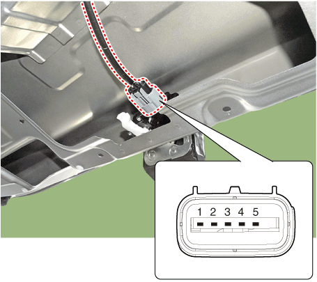
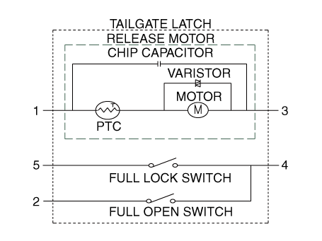
Disconnect the 4P connector from the actuator.
|
| 3. |
Check actuator operation by connecting power and ground according to
the table.
|
Hood Switch
| 1. |
Disconnect the connector and bolts from the hood switch.
|
| 2. |
Check for continuity between the terminals and ground according to the
table.
|
 Smart Key System
Description and operation Description The SMART KEY system is a system that allows the user to access and operate a vehicle in a very convenient way. To access the vehicle, no traditional key or remote ...
 Integrated Body Control Unit (IBU)
Description and operation Description Body Control Module Controls The Followings – Wiper & Washer Control – Defroster Control – Driving Control – Tailgate Control – Window Control – Interior ...
See also:
Auto Head Lamp Leveling
Unit. Schematic Diagrams
Circuit Diagram ...
Horn
To sound the horn, press the area indicated by the horn symbol on your steering wheel (see illustration). The horn will operate only when this area is pressed. Check the horn regularly to be sure it operates ...
Instrument Cluster. Description
and Operation
Description Communication Network Diagram Abbreviation Explanation C_CAN Chassis Controller Area Network B_CAN Body Controller Area Network MM_CAN Multi media Controller Area Network SMK Smart Key ECU ...

