 Hyundai Santa Fe (TM): Rear Heater
Rear Heater Unit. Components and components location
| Component Location |
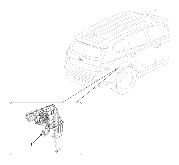
| 1. Rear Heater
& A/C Unit |
| Components |
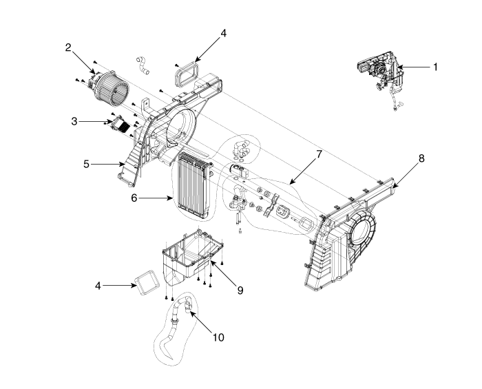
|
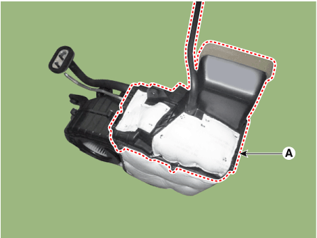
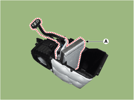
1. Rear heater & blower unit assembly 2. Blower motor assembly 3. Rear power mosfet 4. Duct seal guide 5. Evaporator case [LH] |
6. Evaporator core assembly 7. Evaporator pipe assembly 8. Evaporator case [RH] 9. Evaporator lower case 10. Drain hose assembly |
Rear Heater Unit. Repair procedures
| Replacement |
|

| 1. |
Disconnect the negative (-) battery terminal.
|
| 2. |
Recover the refrigerant with a recovery/charging station.
|
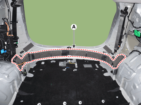
| 3. |
Remove the luggage side trim [RH]
(Refer to Body - "Luggage Side Trim")
|
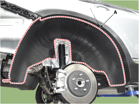
| 4. |
Loosen the mounting screws and separate the rear wheel guard [RH] (A).
|
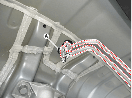
| 5. |
Loosen the mounting nuts and remove the refrigeration line (A).
|

| 6. |
Loosen the rear evaporator pipe mounting bolts.
|
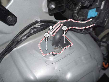
| 7. |
Remove the mounting bolts and remove the rear A/C duct (A).
|
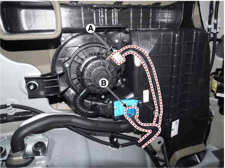
| 8. |
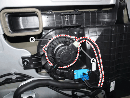
Separate the rear blower motor connector (A) and rear mosfet connector
(B).
|
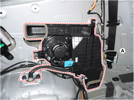
| 9. |
Loosen the mounting bolts and nuts and remove the A/C unit (A).
|
| 10. |
Install in the reverse order of removal.
|
Rear Evaporator Core. Repair procedures
| Replacement |
| 1. |
Remove the rear heater & A/C unit.
(Refer to Rear Heater - "Rear Heater Unit")
|
| 2. |
Loosen the mounting screws and remove the rear A/C lower case (A).
|
| 3. |
Remove the rear evaporator core (A).
|
| 4. |
Install in the reverse order of removal.
|
Rear Blower Motor. Repair procedures
| Replacement |
| 1. |
Disconnect the negative (-) battery terminal.
|
| 2. |
Remove the luggage side trim [RH].
(Refer to Body - "Luggage Side Trim")
|
| 3. |
Separate the blower motor connector (A) and loosen the mounting screws
and remove the blower motor (B).
|
| 4. |
Install in the reverse order of removal.
|
Rear Power Mosfet. Repair procedures
| Inspection |
| 1. |
Turn the ignition switch ON.
|
| 2. |
Manually operate the control switch and measure the voltage of the blower
motor.
|
| 3. |
Select the control switch to raise the voltage until it reaches high
speed.
Specification
|
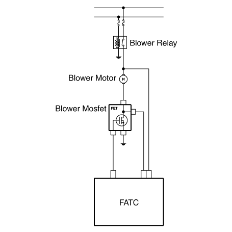
| 4. |
If the measured voltage is not within specification, substitute with
a known-good power mosfet and check for proper operation.
|
| 5. |
Replace the power mosfet if it is proved that there is a problem with
it.
|
| Replacement |
| 1. |
Disconnect the negative (-) battery terminal.
|
| 2. |
Remove the luggage side trim [RH].
(Refer to Body -"Luggage Side Trim")
|
| 3. |
Separate the connector and loosen the mounting screw ,remove the power
mosfet (A).
|
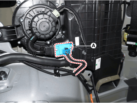
| 4. |
Install in the reverse order of removal.
|
 Blower
Blower Unit. Components and components location Components Location 1. Blower unit assembly Components 1. Blower unit assembly 2. Inlet case [LH] 3. Inlet seal 4. Inlet case [RH] 5. Intake actuator 6. ...
 Controller
Heater & A/C Control Unit (Manual). Components and components location Component Connector Pin Function Pin No Connector A Connector B 1 Battery Low 2 ISG B+ Common 3 ILL+ (TAIL) Ground 4 Sensor REF ...
See also:
SS-A Solenoid Valve(ON/OFF). Schematic Diagrams
Circuit Diagram ...
Shift Lever. Components and Components Location
Components 1. Console upper cover 2. Shift lever assembly 3. Shift cable assembly 4. Shift lever knob & boots assembly 5. Manual control lever 6. Retainer ...
Front Wheel Repair procedures
Removal 1. Remove the driveshaft and axle. 2. Remove the propeller shaft (A). Tightening torque : 49.0~68.6N.m (5.0~7.0kgf.m, 36.2~50.6lb-ft) 3. Loosen the transfer upper & lower mounting bolts. (transfer ...
