 Hyundai Santa Fe (TM): Rear Suspension System
Components and components location
| Components |
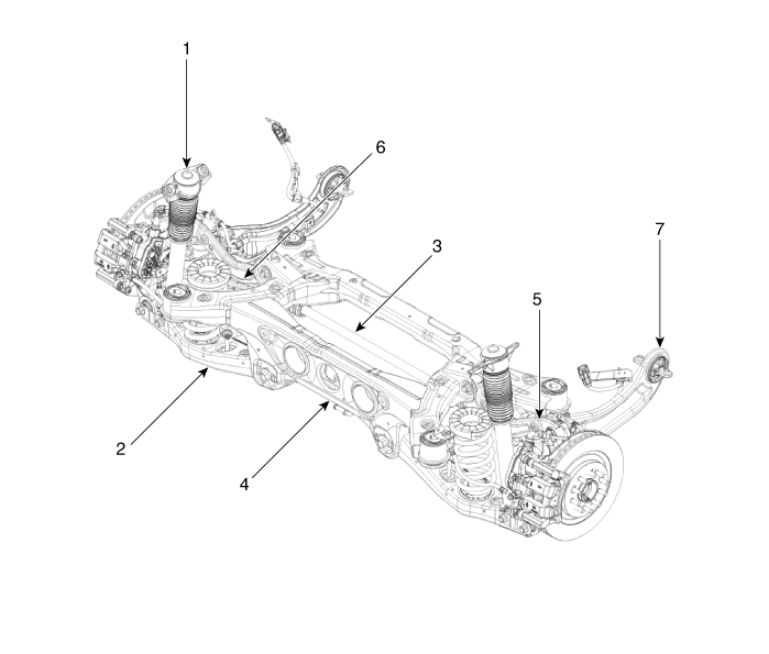
| 1. Rear shock
absorber 2. Rear lower arm 3. Rear stabilizer bar 4. Rear cross member |
5. Rear upper
arm 6. Rear assist arm 7. Trailing arm |
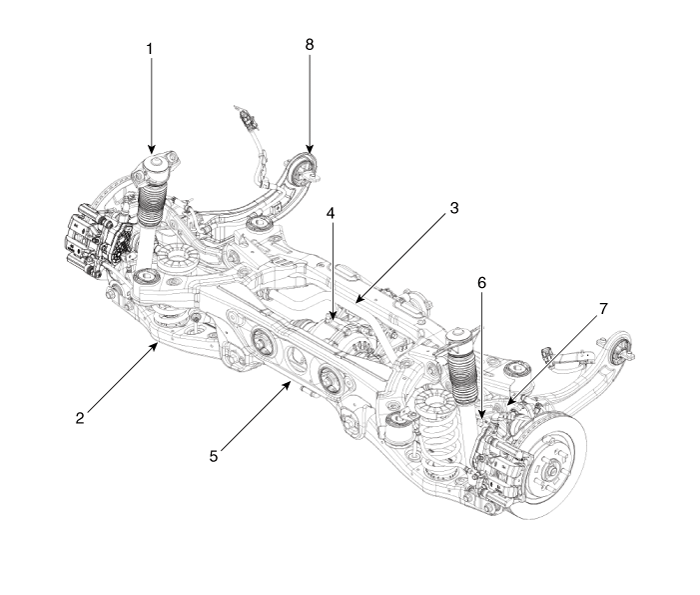
| 1. Rear shock
absorber 2. Rear lower arm 3. Rear stabilizer bar 4. Rear differential carrier |
5. Rear cross
member 6. Rear driveshaft 7. Rear upper arm 8. Trailing arm |
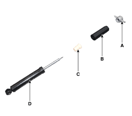
Rear Shock Absorber. Components and components location
| Components |
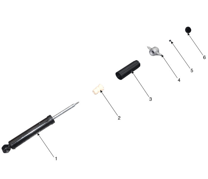
| 1. Rear shock
absorber 2. Dust cover 3. Bumper rubber |
4. Insulator
assembly 5. Lock nut 6. Insulator cap |
Rear Shock Absorber. Repair procedures
| Removal |
| 1. |
Loosen the wheel nuts slightly.
Raise the vehicle, and make sure it is securely supported.
|
| 2. |
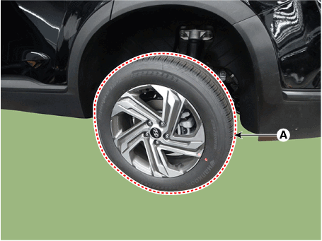
Remove the rear wheel and tire (A) from rear hub.
|

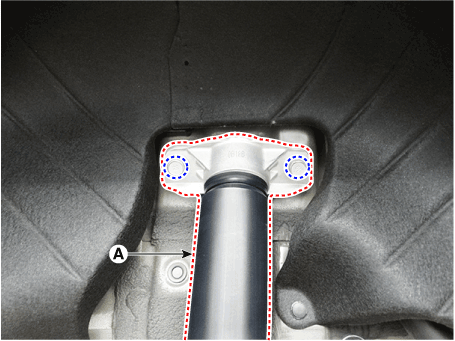
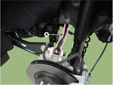
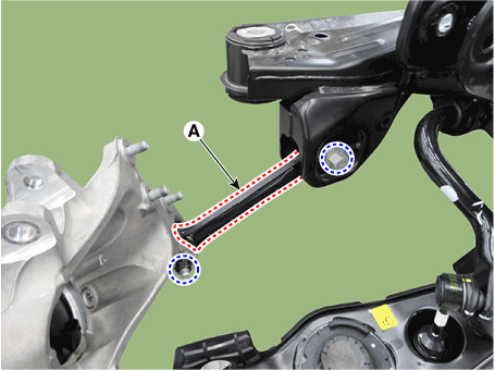
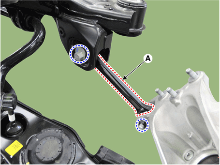
| 3. |
Remove the rear shock absorber (A) from the body by loosening the bolt.
|
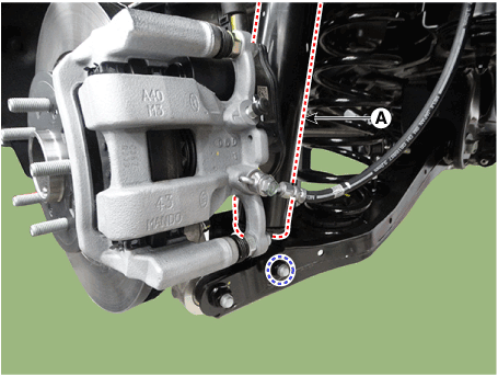
| 4. |
Loosen the bolt and nut and then remove the rear shock absorber (A)
from the lower arm.
|
| Disassembly |
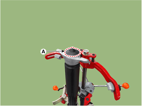
| 1. |
Remove the insulator cap (A).
|
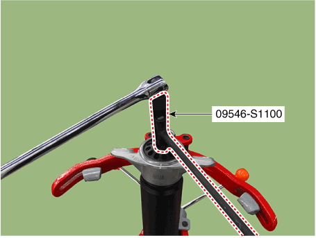
| 2. |
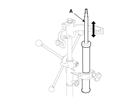
Using the special tool (09546-S1100), install the self locking nut.
|
| 3. |
Separate the Insulator assembly (A), dust cover (B), bumper rubber (C),
shock absorber (D).
|
| Inspection |
| 1. |
Check the rubber parts for damage or deterioration.
|
| 2. |
Check the shock absorber for abnormal resistance or unusual sounds.
|
| Disposal |
| 1. |
Fully extend the shock absorber rod.
|
| 2. |
Drill a hole to remove gas from the cylinder.
|
| Reassembly |
| 1. |
To reassembly, reverse the disassembly procedure.
|
| 2. |
Using SST (09546-3X100), install the lock nut.
|
| 3. |
Install the lock nut cover (A).
|
| Installation |
| 1. |
To install, reverse the removal procedures.
|
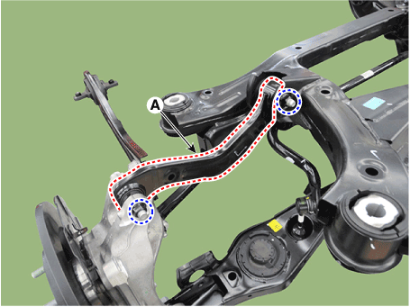
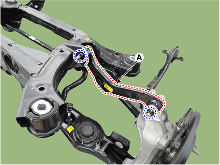
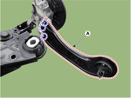
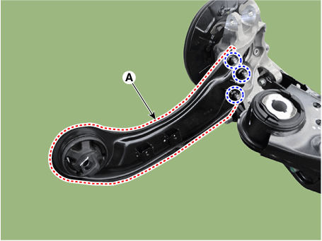
Rear Upper Arm. Repair procedures
| Removal |
| 1. |
Loosen the wheel nuts slightly.
Raise the vehicle, and make sure it is securely supported.
|
| 2. |
Remove the rear wheel and tire (A) from rear hub.
|
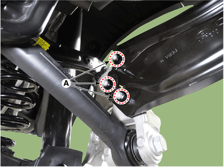
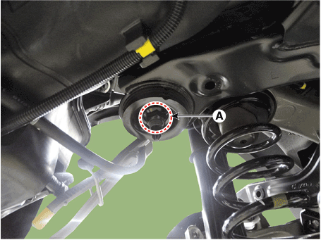
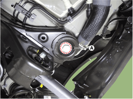
| 3. |
Remove the rear upper arm (A) after loosening the mounting bolt and
nut.
|
| Inspection |
| 1. |
Check the bushing for wear and deterioration.
|
| 2. |
Check the rear upper arm or damage and deformation.
|
| 3. |
Check for all bolts and nut.
|
| Installation |
| 1. |
To install, reverse the removal procedures.
|
| 2. |
Check the alignment.
(Refer to Suspension System - "Alingment")
|
Rear Lower Arm. Repair procedures
| Removal |
| 1. |
Loosen the wheel nuts slightly.
Raise the vehicle, and make sure it is securely supported.
|
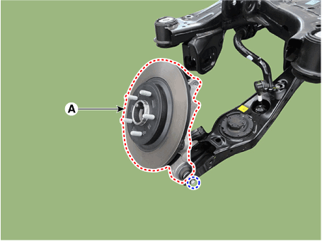
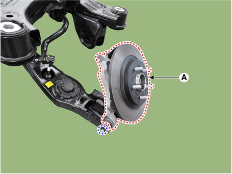
| 2. |
Remove the rear wheel and tire (A) from rear hub.
|
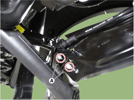
| 3. |
Remove the rear lower arm from the rear axle after loosening the mounting
bolts and nuts (A).
|
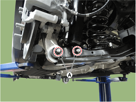
| 4. |
Remove the stabilizer bar link from the rear lower arm after loosening
the mounting nut (A).
|
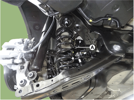
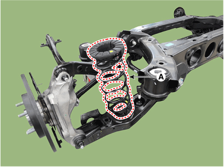
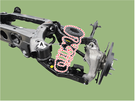
| 5. |
Remove the coil spring (A).
|
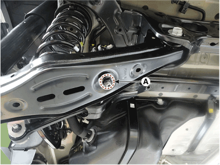
| 6. |
Remove the rear lower arm (A) after loosening the mounting bolt and
nut.
|
| Inspection |
| 1. |
Check the bushing for wear and deterioration.
|
| 2. |
Check the rear lower arm for deformation.
|
| 3. |
Check the coil spring and spring pad for deterioration and deformation.
|
| 4. |
Check for all bolts and nut.
|
| Installation |
| 1. |
To install, reverse the removal procedures.
|
| 2. |
Check the alignment.
(Refer to Suspension System - "Alingment")
|
Rear Coil Spring. Repair procedures
| Removal |
| 1. |
Loosen the wheel nuts slightly.
Raise the vehicle, and make sure it is securely supported.
|
| 2. |
Remove the rear wheel and tire (A) from rear hub.
|
| 3. |
Remove the rear lower arm from the rear axle after loosening the mounting
bolts and nuts (A).
|
| 4. |
Remove the stabilizer bar link from the rear lower arm after loosening
the mounting nut (A).
|
| 5. |
Remove the coil spring (A).
|
| Inspection |
| 1. |
Check the spring for distortion, aging or damage.
|
| 2. |
Check the spring upper pad and lower pad for aging or damage.
|
| Installation |
| 1. |
To install, reverse the removal procedures.
|
| 2. |
Check the alignment.
(Refer to Suspension System - "Alingment")
|
Trailing Arm. Repair procedures
| Removal |
| 1. |
Loosen the wheel nuts slightly.
Raise the vehicle, and make sure it is securely supported.
|
| 2. |
Remove the rear wheel and tire (A) from rear hub.
|
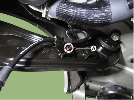
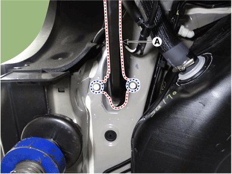
| 3. |
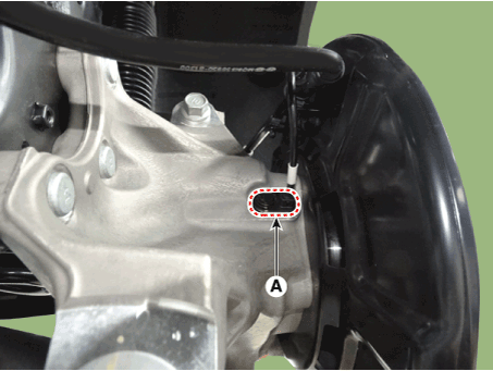
Loosen the wheel speed sensor cable bracket mounting nuts (A).
|
| 4. |
Loosen the wheel speed sensor cable bracket mounting bolts (A).
|
| 5. |
Loosen the trailing arm mounting bolts (A).
|
| 6. |
Remove the trailing arm (A) after loosening the mounting bolts.
|
| Inspection |
| 1. |
Check the bushing for wear and deterioration.
|
| 2. |
Check for all bolts and nuts.
|
| Installation |
| 1. |
To install, reverse the removal procedures.
|
| 2. |
Check the alignment.
(Refer to Suspension System - "Alingment")
|
Rear Assist Arm. Repair procedures
| Removal |
| 1. |
Loosen the wheel nuts slightly.
Raise the vehicle, and make sure it is securely supported.
|
| 2. |
Remove the rear wheel and tire (A) from rear hub.
|
| 3. |
Remove the rear assist arm (A) after loosening the mounting bolts and
nuts.
|
| Inspection |
| 1. |
Check the bushing for wear and deterioration.
|
| 2. |
Check for all bolts and nuts.
|
| Installation |
| 1. |
To install, reverse the removal procedures.
|
| 2. |
Check the alignment.
(Refer to Suspension System - "Alingment")
|
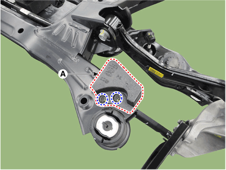
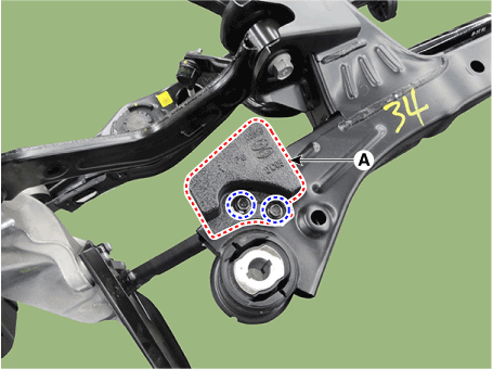
Rear Stabilizer Bar. Repair procedures
| Removal |
| 1. |
Raise the vehicle, and make sure it is securely supported.
|
| 2. |
In the case of 4WD vehicle, remove the rear differential assembly.
(Refer to Driveshaft and axle - "Rear Differential Carrier")
|
| 3. |
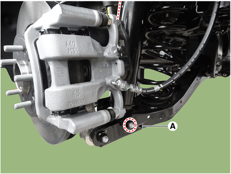
Remove the rear stabilizer link after loosening the mounting nut (A).
|
| 4. |
Remove the rear stabilizer bar (A) after loosening the mounting bolts.
|
| Inspection |
| 1. |
Check the rear stabilizer bar for deformation.
|
| 2. |
Check the rear stabilizer link ball joint for damage.
|
| Installation |
| 1. |
To install, reverse the removal procedures.
|
| 2. |
Check the alignment.
(Refer to Suspension System - "Alingment")
|
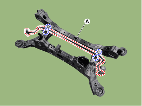
Rear Cross Member. Repair procedures
| Removal |
| 1. |
Loosen the wheel nuts slightly.
Raise the vehicle, and make sure it is securely supported.
|
| 2. |
Remove the front wheel and tire (A) from the front hub.
|
| 3. |
Remove the rear brake caliper.
(Refer to Brake System - "Rear Disc Brake")
|
| 4. |
In the case of 4WD vehicle, remove the rear differential assembly.
(Refer to Driveshaft and axle - "Rear Differential Carrier")
|
| 5. |
Remove the center muffler.
(Refer to Engine Mechanical System - "Muffler")
|
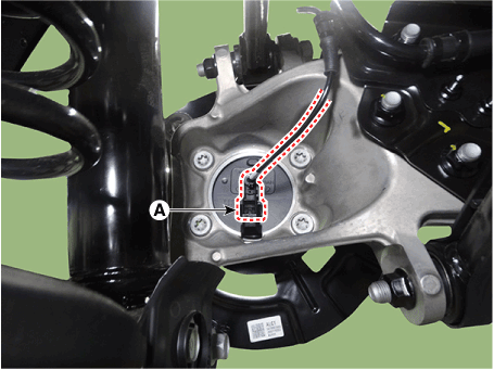
| 6. |
Disconnect the rear wheel speed sensor connector (A).
[2WD]
|
| 7. |
Remove the rear wheel speed sensor (A) after loosening the mounting
bolt.
[4WD]
|
| 8. |
Loosen the wheel speed sensor cable bracket mounting nuts (A).
|
| 9. |
Loosen the wheel speed sensor cable bracket mounting bolts (A).
|
| 10. |
Remove the trailing arm (A) after loosening the mounting bolts.
|
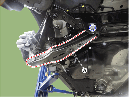
| 11. |
Support the jack on the lower part of the cross member.
|
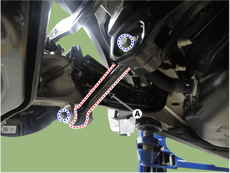
| 12. |
Loosen the bolt and nut and then remove the rear shock absorber (A)
from the lower arm.
|
| 13. |
|
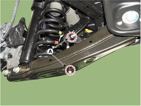
| 14. |
Loosen the cross member mounting bolts (A).
|
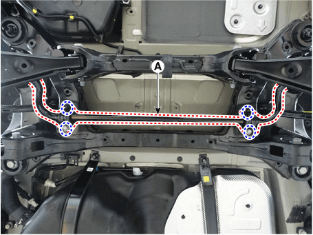
| 15. |
Remove the rear cross member.
|
| 16. |
Remove the coil spring (A).
[LH]
[RH]
|
| 17. |
Remove the damper (A) after loosening the mounting bolts.
[LH]
[RH]
|
| 18. |
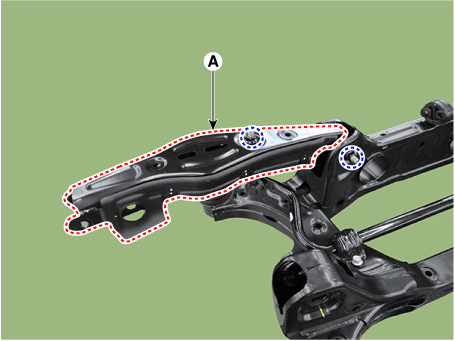
Remove the rear upper arm (A) after loosening the mounting bolts and
nuts.
[LH]
[RH]
|
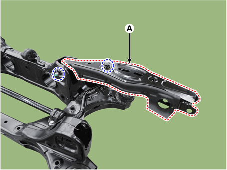
| 19. |
Remove the trailing arm (A) after loosening the mounting nuts.
[LH]
[RH]
|
| 20. |
Remove the rear assist arm (A) after loosening the mounting bolts and
nuts.
[LH]
[RH]
|
| 21. |
Remove the rear carrier (A) from the rear lower arm after loosening
the mounting bolt and nut.
[LH]
[RH]
|
| 22. |
Remove the rear lower arm (A) after loosening the mounting bolts and
nuts.
[LH]
[RH]
|
| 23. |
Remove the rear stabilizer bar (A) after loosening the mounting bolts.
|
| Inspection |
| 1. |
Check the bushing for wear and deterioration.
|
| 2. |
Check for all bolts and nuts.
|
| Installation |
| 1. |
To install, reverse the removal procedures.
|
| 2. |
Check the alignment.
(Refer to Suspension System - "Alingment")
|
 Front Suspension System
Components and components location Components Location 1. Front sub frame 2. Drive shaft 3. Steering gear box 4. Front stabilizer bar 5. Front lower arm 6. Front knuckle assembly Front Strut Assembly. ...
 Tires/Wheels
Tire. Repair procedures Tire Wear • Using tires and wheel other than the recommended sizes could cause unusual handling characteristics and poor vehicle control, resulting in a serious accident. ...
See also:
Fuel requirements
Your new vehicle is designed to use only unleaded fuel having a pump octane number ((R+M)/2) of 87 (Research Octane Number 91) or higher. Your new vehicle is designed to obtain maximum performance with ...
Troubleshooting
Troubleshooting Problem Symptoms Table Before replacing or repairing air conditioning components, first determine if the malfunction is due to the refrigerant charge, air flow or compressor. Use the table ...
Washer fluid
Checking the washer fluid level The reservoir is translucent so that you can check the level with a quick visual inspection. Check the fluid level in the washer fluid reservoir and add fluid if necessary. ...
