 Hyundai Santa Fe (TM): Tires/Wheels
Tire. Repair procedures
| Tire Wear |
|
| 1. |
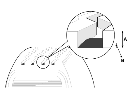
Measure the tread depth of the tires.
|
| 2. |
If the remaining tread depth (A) is less than the limit, replace the
tire.
|
Tire Rotation
| Checking For Pull And Wander |
If the steering pulls to one side, rotate the tires according to the following
wheel rotation procedure.
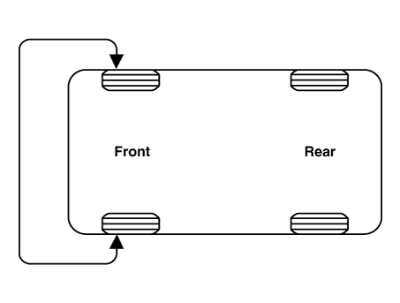
| 1. |
Rotate the front right and front left tires, and perform a road test
in order to confirm vehicle stability.
|
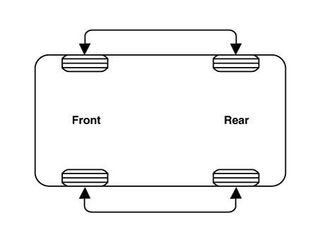
| 2. |
If the steering pulls to the opposite side, rotate the front and rear
tires, and perform a road test again.
|
| 3. |
If the steering continues to pull to one side, rotate the front right
and left tires again, and perform a road test.
|
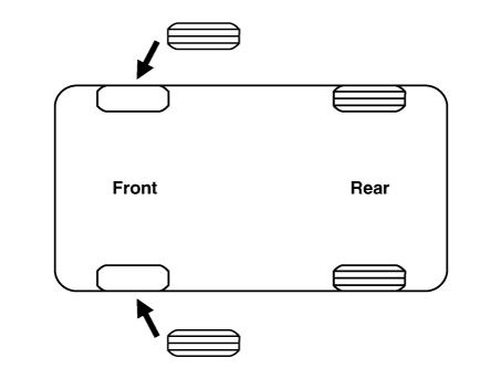
| 4. |
If the steering continues to pull to the opposite side, replace the
front wheels with new ones.
|
| Removal |
| 1. |
Remove valve core and deflate the tire.
|
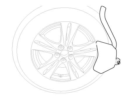
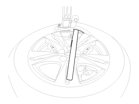
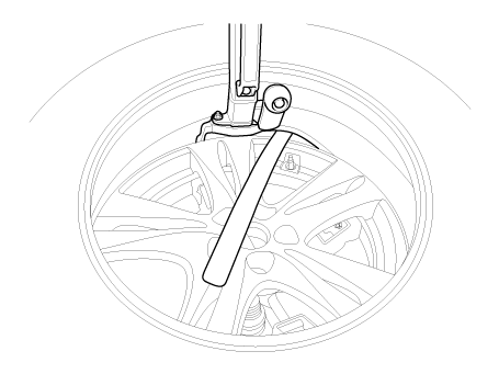
| 2. |
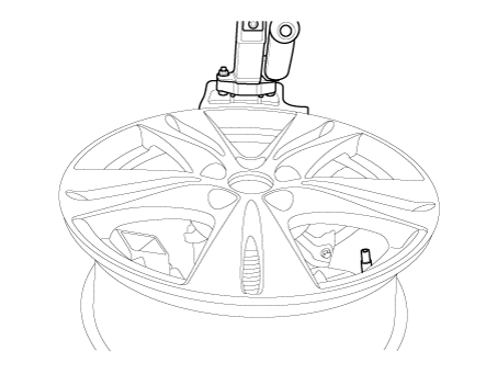
Remove the side of the tire bead area from the wheel using tire changing
machine .
|
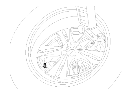
| 3. |
Rotate the wheel clockwise.
|
| Installation |
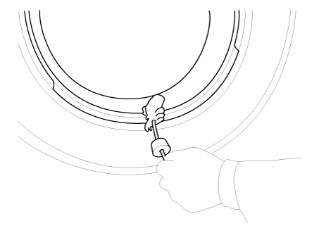
| 1. |
Apply tire soap or lubrication to the top and bottom tire beads.
|
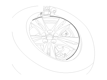
| 2. |
To fit the bottom bead, position the valve at the 5 o’clock position
relative to the head on the tire changing machine.
|
| 3. |
Place the tire on the rim so the bottom bead touches the edge of the
rim after the valve (6 o’clock). Rotate the rim clockwise, and push
down on the tire at the 3 o’clock position to fit bottom bead.
|
| 4. |
After bottom bead is on tire, rotate the rim until the valve is at the
5 o’clock position relative to the head on the tire changing machine.
Push down on the tire at the 3 o’clock position and rotate the rim clockwise
to fit the top bead.
|
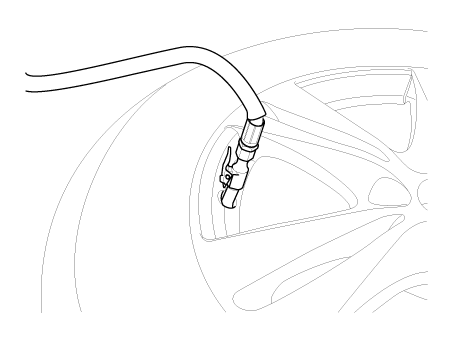
| 5. |
Inflate the tire until both beads seat.
|
Wheel. Components and components location
| Components |
|
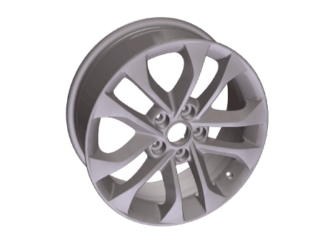
17 inch (7.0J X 17) |
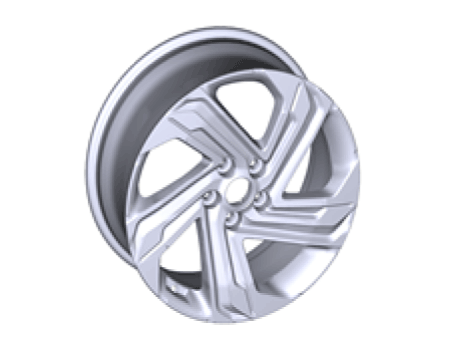
18 inch (7.5J X 18) |
|
|
|
|
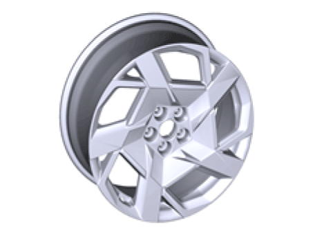
20 inch (8.5J X 20) |
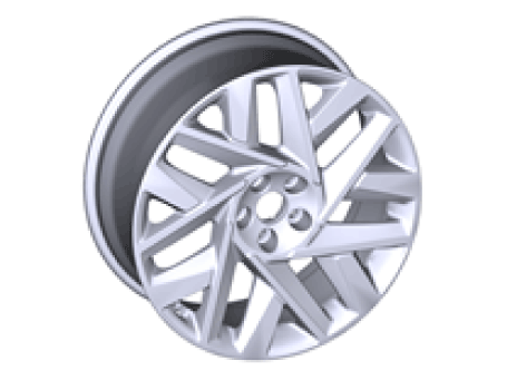
20 inch (8.5J X 20) |
|
|
|
Wheel. Repair procedures
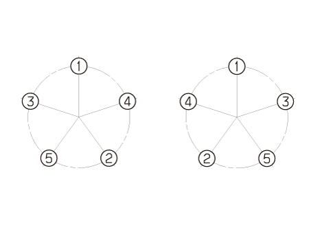
| Hub nut tightening sequence |
| 1. |
Tighten the hub nuts as follows.
|
Run out inspection
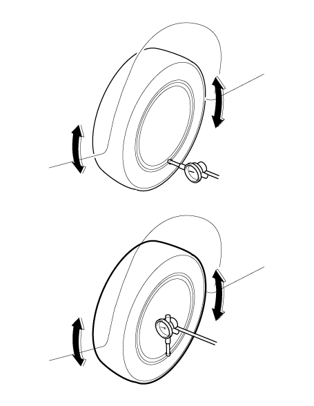
| 1. |
Jack up the vehicle.
|
| 2. |
Measure the wheel Run-out by using a dial indicator as illustration
below.
|
| 3. |
If measured value exceeds the standard value, replace the wheel.
|
Alignment. Repair procedures
| Front Wheel Alignment |
|
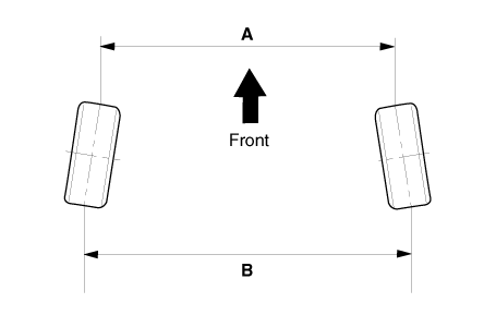
Toe
|
B - A > 0 : Toe in
B - A < 0 : Toe out
|
Toe adjustment
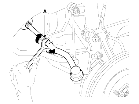
| 1. |
Loosen the tie rod end lock nut.
|
| 2. |
Remove the bellows clip to prevent the bellows frombeing twisted.
|
| 3. |
Adjust the toe by screwing or unscrewing the tie rod.Toe adjustment
should be made by turning the rightand left tie rods by the same amount.
|
| 4. |
When completing the toe adjustment, install thebellows clip and tighten
the tie rod end lock nut tospecified torque.
|
Camber
|
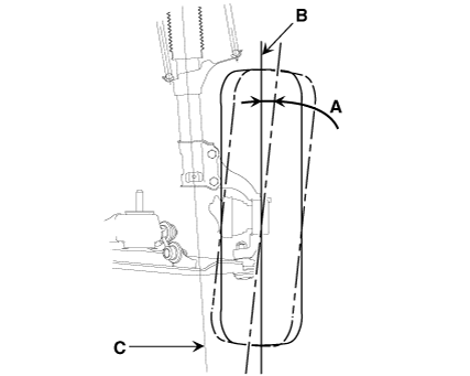
Camber : -0.5° ± 0.5°
|
When the wheel tilts out at the top, then the camber ispositive (+). When the
wheel tilts in at the top, then the camber isnegative (-). Camber and Caster
are pre-set at the factory, so they donot need to be adjusted. If the camber
and caster are notwithin the standard value, replace or repair the damagedparts
and then inspect again.
|
ITEM |
Description |
|
A |
Positive camber angle |
|
B |
True vertical |
|
C |
Strut centerline |
Caster
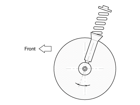
Caster is the tilting of the strut axis either forward or backward from vertical.
A backward tilt is positive (+) and a forward tilt is negative (-).
Caster is pre-set at the factory and doesn't need to be adjusted. If the caster
is not within the standard value, replace the bent or damaged parts.
|
Caster : 4.34° ± 0.5°
|
King-pin angle
|
King-pin : 13.8° ± 0.5°
|
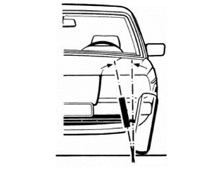
|
| Rear Wheel Alignment |
|
Toe

|
B - A > 0: Toe in (+)
B - A < 0: Toe out (-)
|
Toe adjustment
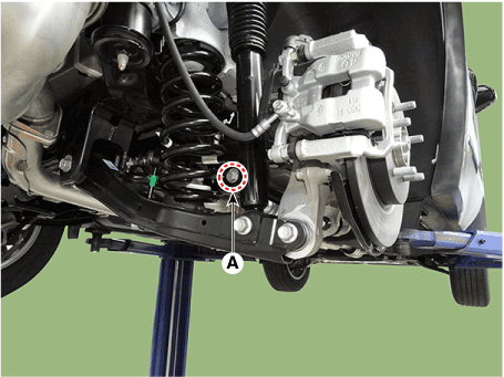
| 1. |
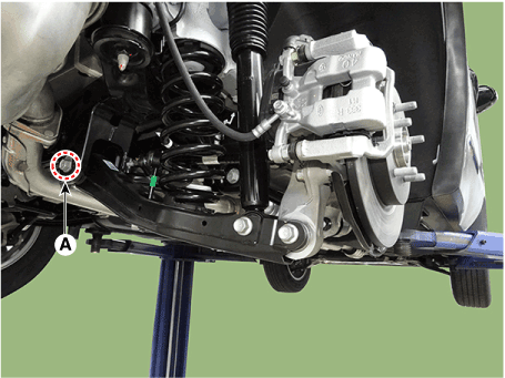
Loosen the nut holding the assist arm cam bolt (A).
|
| 2. |
Adjust rear toe by turning the rear assist arm cam bolt (A) clockwise
or counterclockwise. Toe adjustment should be made by turning the right
and left cam bolt by the same amount.
|
| 3. |
When completing the toe adjustment, tighten the nut to specified torque.
|
Camber
| 1. |
Loosen the nut holding the rear lower arm cam bolt (A).
|
| 2. |
Adjust rear camber by turning the rear lower arm cam bolt (A) clockwise
or counter clockwise. Rear camber adjustment should be made by turning
the right and left cam bolt by the same amount.
|
| 3. |
When completing the toe adjustment, tighten the nut to specified torque.
|
 Rear Suspension System
Components and components location Components [2WD] 1. Rear shock absorber 2. Rear lower arm 3. Rear stabilizer bar 4. Rear cross member 5. Rear upper arm 6. Rear assist arm 7. Trailing arm [4WD] 1. Rear ...
 Tire Pressure Monitoring System
Components and components location Components Location 1. Receiver 2. TPMS Sensor (FL) 3. TPMS Sensor (RL) 4. TPMS Sensor (RR) 5. TPMS Sensor (FR) Description and operation Description TREAD Lamp – Tire ...
See also:
Front Body. Body Repair
Front Body A * These dimensions indicated in this figure are actual-measurement dimensions. [ Unit : mm (inch) ] Front Body B * These dimensions indicated in this figure are actual-measurement dimensions. ...
Door Ajar Warning Light
This warning light illuminates: When a door is not closed securely. ...
Driving your vehicle
WARNING - ENGINE EXHAUST CAN BE DANGEROUS! Engine exhaust fumes can be extremely dangerous. If, at any time, you smell exhaust fumes inside the vehicle, open the windows immediately. • Do not inhale ...


