General safety information and caution
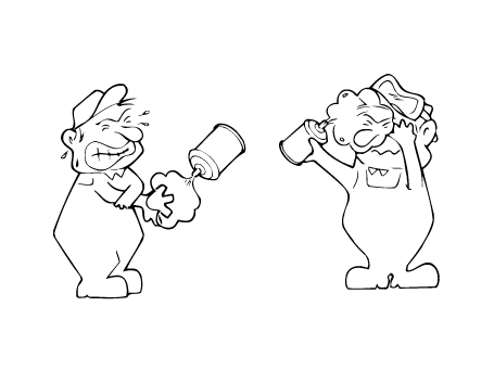
When Handling Refrigerant
|
1. |
R-134a liquid refrigerant is highly volatile. A drop on the skin of
your hand could result in localized frostbite. When handling the refrigerant,
be sure to wear gloves.
|
|
2. |
It is standard practice to wear goggles or glasses to protect your eyes,
and gloves to protect your hands. If refrigerant splashes into your
eyes, wash them with clean water immediately.
|
|
3. |
The R-134a container is highly pressurized. Never leave it in a hot
place, and check if storage temperature is below 52°C (126°F)
|
|
4. |
An electronic leak detector should be used to check the system for refrigerant
leakage. Bear in mind that the R-134a, upon coming into contact with
flame, produces phosgene, a highly toxic gas.
|
|
5. |
Use only recommended lubricant for R-134a systems. If lubricants other
than the recommended one used, system failure may occur.
|
|
6. |
PAG lubricant absorbs moisture from the atmosphere at a rapid rate,
therefore the following precautions must be observed:
| –
|
When removing refrigerant components from a vehicle, cap the
components immediately to prevent entry of moisture.
|
| –
|
When installing refrigerant components to a vehicle, do not
remove the cap until just before connecting the components.
|
| –
|
Complete the connection of all refrigerant tubes and hoses without
delay to prevent the A/C system from taking on moisture.
|
| –
|
Use the recommended lubricant from a sealed container only.
|
|
|
7. |
If an accidental discharge in the system occurs, ventilate the work
area before resume of service.
|
When Replacing Parts on A/C System
|
1. |
Never open or loosen a connection before discharging the system.
|
|
2. |
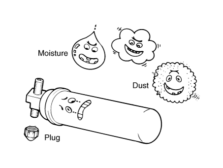
Seal the open fittings of components with a cap or plug immediately
to prevent intrusion of moisture or dust.
|
|
3. |
Do not remove the sealing caps from a replacement component until it
is ready to be installed.
|
|
4. |
Before connecting an open fitting, always install a new sealing ring.
Coat the fitting and seal with refrigerant oil before making the connection.
|
When Installing Connecting Parts
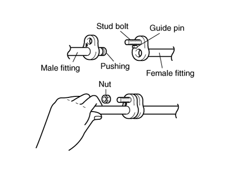
Flange With Guide Pin
Check the new O-ring for damage (use only the specified) and lubricate by using
compressor oil. Tighten the nut to the specified torque.
Handling Tubing and Fittings
The internal parts of the refrigeration system will remain in a state of chemical
stability as long as pure moisture-free refrigerant and refrigerant oil are
used. Abnormal amounts of dirt, moisture or air can upset the chemical stability
and cause problems or serious damage.
The Following Precautions Must Be Observed
|
1. |
When it is necessary to open the refrigeration system, have everything
you will need to service the system ready so the system will not be
left open any longer than necessary.
|
|
2. |
Cap or plug all lines and fittings as soon as they are opened to prevent
entrance of dirt and moisture.
|
|
3. |
All lines and components in parts stock should be capped or sealed until
they are ready to be used.
|
|
4. |
Never attempt to rebind formed lines to fit. Use the correct line for
the installation you are servicing.
|
|
5. |
All tools, including refrigerant dispensing manifold, gauge set manifold
and test hoses, should be kept clean and dry.
|
| •
|
The R-1234yf liquid refrigerant is a flammable gas. The gas
reduces oxygen available for breathing and causes asphyxiation
in high concentrations. The victim will not realize that he/she
is suffocating.
|
| •
|
Inhalation may cause central nervous system effects and may
cause drowsiness and dizziness.
|
| •
|
Ingestion may cause gastrointestinal discomfort. It may cause
skin irritation, eye irritation and respiratory tract irritation.
Do not breathe vapour. Avoid contact with skin, eyes and clothing.
|
|
|
In case of emergency, the following precautions must be observed; First
aider needs to protect himself. Take off all contaminated clothing immediately.
| –
|
Inhalation : Move to fresh air. If not breathing, give artificial
respiration. If breathing is difficult, give oxygen. Use oxygen
as required, provided a qualified operator is present. Call
a physician.
|
| –
|
Skin contact : After contact with skin, wash immediately with
plenty of water. Rapid evaporation of the liquid may cause frostbite.
If there is evidence of frostbite, bathe (do not rub) with lukewarm
(not hot) water. If water is not available, cover with a clean,
soft cloth or similar covering. Call a physician. Wash contaminated
clothing before re-use.
|
| –
|
Eye contact : Rinse immediately with plenty of water, also under
the eyelids, for at least 15 minutes. In case of frostbite water
should be lukewarm, not hot. Call a physician.
|
| –
|
Ingestion : Unlikely route of exposure. As this product is a
gas, refer to the inhalation section. Do not induce vomiting
without medical advice. If conscious, drink plenty of water.
Never give anything by mouth to an unconscious person. Call
a physician immediately.
|
|
|
When handling refrigerant, the following precautions must be observed
:
| –
|
Wear personal protective equipment.
|
| –
|
Do not breathe vapour.
|
| –
|
Avoid contact with skin, eyes and clothing.
|
| –
|
Ensure that eyewash stations and safety showers are close to
the workstation location.
|
| –
|
Use only in well-ventilated areas.
|
| –
|
Protect from sunlight and do not expose to temperatures exceeding
52°C (125°F).
|
| –
|
Follow all standard safety precautions for handling and use
of compressed gas cylinders.
|
| –
|
Use authorized cylinders only.
|
| –
|
Protect cylinders from physical damage.
|
| –
|
Do not puncture or drop cylinders, expose them to open flame
or excessive heat.
|
| –
|
Do not remove screw cap until immediately ready for use.
|
| –
|
Always replace cap after use.
|
| –
|
Container is hazardous when empty.
|
| –
|
Prevent the creation of flammable or explosive concentrations
of vapour in air and avoid vapour concentration higher than
the occupational exposure limits.
|
| –
|
Keep product and empty container away from heat and sources
of ignition.
|
| –
|
Do not pressurize, cut, weld, braze, solder, drill, grind or
expose containers to heat or sources of ignition.
|
| –
|
Take measures to prevent the build up of electrostatic charge.
|
| –
|
Electrical equipment should be protected to the appropriate
standard.
|
| –
|
Use explosion-proof equipment.
|
| –
|
No sparking tools should be used.
|
|
| –
|
When storing the refrigerant, the following precautions must
be observed :
|
| –
|
Pressurized container. Protect from sunlight and do not expose
to temperatures exceeding 52°C (125°F). Do not pierce or burn,
even after use.
|
| –
|
Keep containers tightly closed in a dry, cool and well-ventilated
place.
|
| –
|
Keep away from heat and sources of ignition.
|
| –
|
Storage rooms must be properly ventilated.
|
| –
|
Ensure adequate ventilation, especially in confined areas.
|
| –
|
Protect cylinders from physical damage.
|
| –
|
Store away from incompatible substances.
|
| –
|
Store in original container.
|
|
| •
|
Un-controlled release of R-1234yf refrigerant in the work area
may result in high concentrations of R-1234yf that can be flammable.
Servicing of R-1234yf systems shall only be done in well ventilated
work areas.
|
| •
|
When servicing, maintaining or repairing A/C systems using flammable
refrigerants (mildly flammable or higher) the work place shall
meet all applicable national, regional or local regulations
for work place safety as related to high pressure or flammable
gases.
|
|
| •
|
Avoid breathing any refrigerant vapor and lubricant mist. To
remove refrigerant from a A/C system, use service equipment
designed for recovery and removal that is certified to meet
the requirements of the appropriate SAE Standards.
|
| •
|
Do not increase pressure, in any R-134a, or R-1234yf mobile
A/C system with shop air or another refrigerant such as HCFC-22
(R-22) for leak checking, due to potential chemical reactions,
flammability of air/R-134a at elevated pressure, contamination
of the system, and possible structural damage to the system.
|
| •
|
To prevent an accumulation of refrigerant in case of a major
refrigerant leak, open vehicle windows and doors when charging
an A/C system
|
| •
|
To prevent accidental release of refrigerant and minimize safety
concerns, the installation of any refrigerant service equipment
to the vehicle shall only be done with the engine off and after
the refrigerant high side pressure has been reduced (approximately
2 to 3 min).
|
|
| •
|
The proper handling procedures should be followed for all refrigerants
as designated by the refrigerant manufacturer’s Material Safety
Data Sheet (MSDS).
|
| •
|
Service personnel shall be aware of the high pressure relief
valve location when servicing the vehicle. Service personnel
shall not be under the vehicle when charging the refrigerant
system due to potential sudden release of the high pressure
relief valve.
|
|
When Handling Refrigerant
| •
|
Some of the practices, techniques and procedures, as well as
the information, tools and equipment which have been commonly
used in mobile air conditioning system diagnosis and service
of R-12 and R-134a are different for A/C systems using R-1234yf.
Modifications and adjustments have to be made based on the individual
characteristics of each refrigerant. No technician may perform
service or repair on a mobile air conditioning system using
R-1234yf without being trained for the refrigerant being handled.
Under the SAE Standard J2845 the refrigerant system should only
be serviced by trained and certified technicians to insure proper
and safe operation.
|
| •
|
Service technicians should always wear proper personal protective
equipment while handling/servicing systems that contain any
refrigerant.
|
| •
|
Service technicians shall read and follow the appropriate Material
Safety Data Sheets (MSDS), which provide information on safety
and the proper personal protective equipment to use.
- All contact with liquid or gaseous refrigerant shall be avoided.
- Goggles with side protection and gloves (insulated against
heat loss and impermeable to refrigerant) shall be worn while
working with the refrigerant circuit.
- Exposure of the skin to refrigerant may result in frostbite,
in which case rub affected area with lukewarm water. A physician
shall be consulted immediately regarding the affected skin areas.
|
| •
|
A physician shall be consulted immediately in the event of complaints
following exposure to high refrigerant concentrations. Complaint
symptoms may include: increased breathing rate, breathlessness,
headache, accelerated pulse, dizziness.
|
| •
|
Avoid breathing A/C refrigerant and lubricant vapor or mist.
To remove refrigerant from the A/C system, use service equipment
designed for recovery of that refrigerant which is certified
to meet the requirements of the appropriate SAE Standards.
|
|
|
1. |
R-1234yf liquid refrigerant is highly volatile. A drop on the skin of
your hand could result in localized frostbite. When handling the refrigerant,
be sure to wear gloves.
|
|
2. |
It is standard practice to wear goggles or glasses to protect your eyes,
and gloves to protect your hands. If the refrigerant splashes into your
eyes, wash them with clean water immediately.
|
|
3. |
The R-1234yf container is highly pressurized. Never leave it in a hot
place, and check storage temperature is below 52°C (125°F).
|
|
4. |
An electronic leak detector should be used to check the system for refrigerant
leakage. Bear in mind that the R-1234yf, upon coming into contact with
flame, produces phosgene, a highly toxic gas.
|
|
5. |
Use only recommended lubricant for R-1234yf systems. If lubricants other
than the recommended one used, system failure may occur.
|
|
6. |
PAG lubricant absorbs moisture from the atmosphere at a rapid rate,
therefore the following precautions must be observed :
| •
|
When removing refrigerant components from a vehicle, cap the
components immediately to prevent entry of moisture.
|
| •
|
When installing refrigerant components to a vehicle, do not
remove the cap until just before connecting the components.
|
| •
|
Complete the connection of all refrigerant tubes and hoses without
delay to prevent the A/C system from taking on moisture.
|
| •
|
Use the recommended lubricant from a sealed container only.
|
|
|
7. |
If an accidental discharge in the system occurs, ventilate the work
area before resume of service.
|
|
8. |
Clean all dirt, grease and debris from and around connection joints
before servicing and disassembly of refrigerant connections.
|
Description and operation
Components and components location
Engine Room
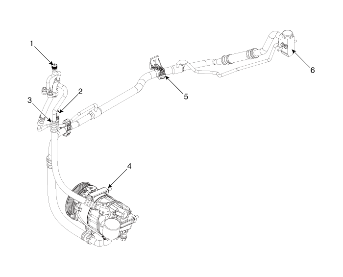
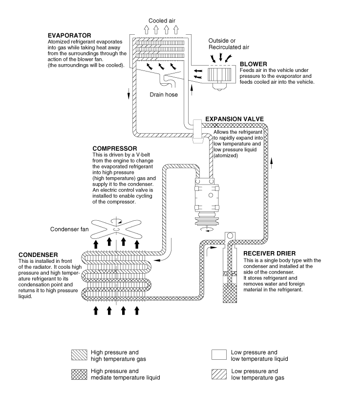
1. Service port
(High pressure)
2. A/C pressure transducer (APT)
3. Service port (Low pressure)
|
4. Compressor
5. Suction & Liquid pipe assembly
6. Expansion valve
|
Interior
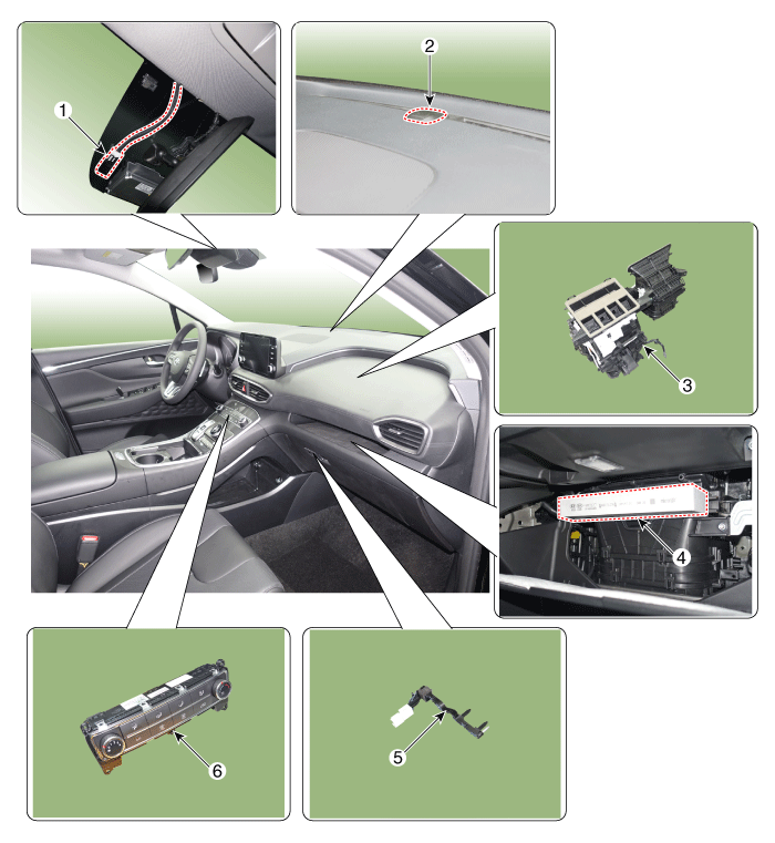
1. Auto defogging
sensor
2. Photo Sensor
3. Heater & Blower unit
|
4. Air filter
5. Evaporator Temperature Sensor
6. Heater & A/C control unit
|
Repair procedures
| Refrigerant System Service
Basics (R-134a) |
Refrigerant Recovery
Use only service equipment that is U.L-listed and is certified to meet the requirements
of SAE J2210 to remove HFC-134a(R-134a) from the air conditioning system.
| •
|
Air conditioning refrigerant or lubricant vapor can irritate
your eyes, nose, or throat.
|
| •
|
Be careful when connecting service equipment.
|
| •
|
Do not breathe refrigerant or vapor.
|
|
If accidental system discharge occurs, ventilate the work area before resume
of service.
Additional health and safety information may be obtained from the refrigerant
and lubricant manufacturers.
|
1. |
Connect an R-134a refrigerant Recovery / Recycling / Charging System
(A) to the high-pressure service port (B) and the low-pressure service
port (C) as shown, following the equipment
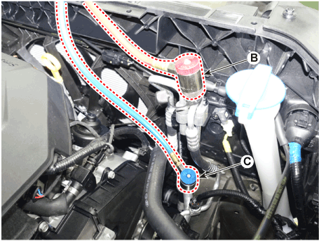
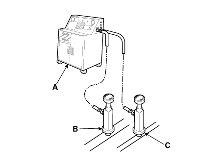
|
|
2. |
Measure the amount of refrigerant oil removed from the A/C system after
the recovery process is completed. Be sure to install the same amount
of new refrigerant oil back into the A/C system before charging.
|
System Evacuation
Use only service equipment that is U.L-listed and is certified to meet the requirements
of SAE J2210 to remove HFC-134a(R-134a) from the air conditioning system.
| •
|
Air conditioning refrigerant or lubricant vapor can irritate
your eyes, nose, or throat.
|
| •
|
Be careful when connecting service equipment.
|
| •
|
Do not breathe refrigerant or vapor.
|
|
If accidental system discharge occurs, ventilate the work area before resume
of service.
Additional health and safety information may be obtained from the refrigerant
and lubricant manufacturers.
|
1. |
When an A/C system has been opened to the atmosphere, such as during
installation or repair, it must be evacuated using a R-134a refrigerant
Recovery/Recycling/Charging system. (If the system has been open for
several days, the receiver/drier should be replaced, and the system
should be evacuated for several hours.)
|
|
2. |
Connect a R-134a refrigerant Recovery/Recycling/Charging system (A)
to the high-pressure service port (B) and the low-pressure service port
(C) as shown, following the equipment manufacturer's instructions.

|
|
3. |
If the low-pressure does not reach more than 93.3 kPa (700 mmHg, 27.6
in.Hg) in 10 minutes, there is probably a leak in the system. Partially
charge the system, and check for leaks (see Refrigerant Leak Test.)
|
|
4. |
Remove the low pressure valve from the low-pressure service port.
|
System Charging
Use only service equipment that is U.L-listed and is certified to meet the requirements
of SAE J2210 to remove HFC-134a(R-134a) from the air conditioning system.
| •
|
Air conditioning refrigerant or lubricant vapor can irritate
your eyes, nose, or throat.
|
| •
|
Be careful when connecting service equipment.
|
| •
|
Do not breathe refrigerant or vapor.
|
|
If accidental system discharge occurs, ventilate the work area before resume
of service.
Additional health and safety information may be obtained from the refrigerant
and lubricant manufacturers.
|
1. |
Connect a R-134a refrigerant
Recovery/Recycling/Charging system (A) to the high-pressure service
port (B) as shown, following the equipment manufacturer's instructions.

|
|
2. |
Add the same amount of new refrigerant oil to the system that was removed
during recovery. Use only specified refrigerant oil. Charge the system
with [Single front only : 650 ± 25g (20.9 ± 0.88oz) , Dual front & rear
: 850 ± 25g (29.9 ± 0.88oz)] R-134a refrigerant. Do not overcharge the
system the compressor will be damaged.
|
Refrigerant Leak Test
Always conduct a leak test with an electronic leak detector whenever leakage
or refrigerant is suspected and when conducting service operations which are
accompanied by disassembly or loosening or connection fittings.
|
In order to use the leak detector properly, read the manual supplied
by the manufacturer.
|
If a gas leak is detected, proceed as follows:
|
1. |
Check the torque on the connection fittings and, if too loose, tighten
to the proper torque. Check for gas leakage with a leak detector (A).
|
|
2. |
If leakage continues even after the fitting has been tightened, discharge
the refrigerant from the system, disconnect the fittings, and check
their seating faces for damage. Always replace, even if the damage is
slight.
|
|
3. |
Check the compressor oil and add oil if required.
|
|
4. |
Charge the system and recheck for gas leaks. If no leaks are found,
evacuate and charge the system again.
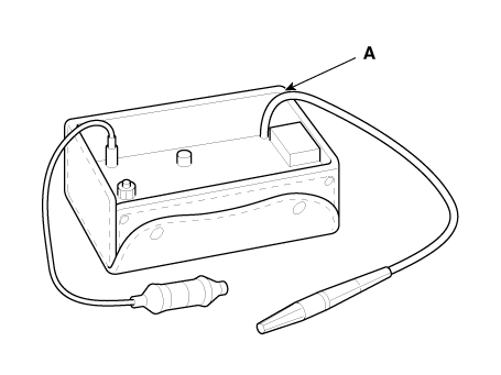
|
| Refrigerant System Service
Basics (R-1234yf) |
Refrigerant Identification
| • |
Do not mix HFO-1234yf (R-1234yf) in the vehicle with other refrigerant,
such as R-12, R-134a and etc.
|
| • |
Use only service equipment that is U.L-listed and is certified to meet
the requirements of SAE standards to recover and recycle R-1234yf from
the air conditioning system. Do not use service equipment for the other
refrigerant, such as R-12, R-134a and etc.
|
| • |
Verify what refrigerant is in the system if there is concern that the
system has been tampered with in any way and check the type and quantity
of refrigerant that shall be in the A/C system and potential issues
arising from accidental or intentional mixing of refrigerants.
|
| • |
Using an SAE certified refrigerant identification device is recommended
to prevent improper recovery and the resulting further spread of contaminated
refrigerant, which could potentially damage other A/C systems and service
equipment. Contaminated refrigerant (blend of more than one refrigerant
or non-system refrigerant) in recovery/recycling equipment could lead
to the potential contamination of more refrigerant.
|
| • |
Certain types of electronic leak detection devices (heated diode or
corona discharge) as well as motors, switches, and controls on recovery
and recycling machines, could generate sparks that could serve as ignition
sources in the presence of refrigerants classified as flammable (A2
or A3) by ASHRAE standard 34 2006.
|
| • |
It is possible that the mixing of refrigerants in a A/C system can result
in higher-than-expected system pressures, system and component damage,
diagnostic errors and/or other potential hazards to people and environment.
|
| • |
In case other refrigerant is mixed, recover the contaminated refrigerant
in the A/C system and dispose it in accordance with all applicable national,
regional or local regulations. Clean inside the A/C system using the
specialized detergent and recharge new refrigerant.
|
Refrigerant Recovery
Use only service equipment that is U.L-listed and is certified to meet the requirements
of SAE standards to remove HFO-1234yf (R-1234yf) from the air conditioning system.
| •
|
Air conditioning refrigerant or lubricant vapor can irritate
your eyes, nose, or throat.
|
| •
|
Be careful when connecting service equipment.
|
| •
|
Do not breathe refrigerant or vapor.
|
|
If accidental system discharge occurs, ventilate work area before resume of
service.
Additional health and safety information may be obtained from the refrigerant
and lubricant manufacturers.
|
1. |
Connect an R-1234yf refrigerant Recovery / Recycling / Charging System
(A) to the high-pressure service port (B) and the low-pressure service
port (C) as shown, following the equipment


|
|
2. |
Measure the amount of refrigerant oil removed from the A/C system after
the recovery process is completed. Be sure to install the same amount
of new refrigerant oil back into the A/C system before charging.
|
System Evacuation
Use only service equipment that is U.L-listed and is certified to meet the requirements
of SAE standards to remove HFO-1234yf (R-1234yf) from the air conditioning system.
| •
|
Air conditioning refrigerant or lubricant vapor can irritate
your eyes, nose, or throat.
|
| •
|
Be careful when connecting service equipment.
|
| •
|
Do not breathe refrigerant or vapor.
|
|
If accidental system discharge occurs, ventilate work area before resume of
service.
Additional health and safety information may be obtained from the refrigerant
and lubricant manufacturers.
|
1. |
When an A/C System has been opened to the atmosphere, such as during
installation or repair, it must be evacuated using an R-1234yf refrigerant
Recovery/Recycling/Charging System. (If the system has been open for
several days, the receiver/dryer should be replaced, and the system
should be evacuated for several hours.)
|
|
2. |
Connect an R-1234yf refrigerant
Recovery/Recycling/Charging System (A) to the high-pressure service
port (B) and the low-pressure service port (C) as shown, following the
equipment manufacturer's instructions.

|
|
3. |
If the low-pressure does not reach more than 87.7 kPa (658 mmHg, 25.9
in.Hg) in 5 minutes, there is probably a leak in the system. Partially
charge the system, and check for leaks (see "Refrigerant Leak Test").
|
|
4. |
Remove the low pressure valve from the low-pressure service port.
|
System Charging
Use only service equipment that is U.L-listed and is certified to meet the requirements
of SAE standards to remove HFO-1234yf (R-1234yf) from the air conditioning system.
| •
|
Air conditioning refrigerant or lubricant vapor can irritate
your eyes, nose, or throat.
|
| •
|
Be careful when connecting service equipment.
|
| •
|
Do not breathe refrigerant or vapor.
|
|
If accidental system discharge occurs, ventilate work area before resume of
service.
Additional health and safety information may be obtained from the refrigerant
and lubricant manufacturers.
|
1. |
Connect an R-1234yf refrigerant
Recovery/Recycling/Charging System (A) to the high-pressure service
port (B) as shown, following the equipment manufacturer's instructions.

|
|
2. |
Add the same amount of new refrigerant oil to the system that was removed
during recovery. Use only specified refrigerant oil. Charge the system
with [Single front only : 625±25g (22.0±0.88oz) , Dual front & rear
: 800±25g (28.2±0.88oz)] R-1234yf refrigerant. Do not overcharge the
system the compressor will be damaged.
|
Refrigerant Leak Test
Always conduct a leak test with an electronic leak detector whenever leakage
or refrigerant is suspected and when conducting service operations which are
accompanied by disassembly or loosening or connection fittings.
| •
|
In order to use the leak detector properly, read the manual
supplied by the manufacturer.
|
|
| •
|
Use only leak detection devices certified to SAE standards for
use with R-1234yf. Certain leak detection devices (heated diode
or corona discharge) could serve as ignition sources in the
presence of hydrocarbons or other flammable refrigerants.
|
|
If a gas leak is detected, proceed as follows :
|
1. |
Check the torque on the connection fittings and, if too loose, tighten
to the proper torque. Check for gas leakage with a leak detector (A).
|
|
2. |
If leakage continues even after the fitting has been tightened, discharge
the refrigerant from the system, disconnect the fittings, and check
their seating faces for damage. Always replace, even if the damage is
slight.
|
|
3. |
Check the compressor oil and add oil if required.
|
|
4. |
Charge the system and recheck for gas leaks. If no leaks are found,
evacuate and charge the system again.

|
Compressor oil. Repair procedures
|
1. |
The R-134a or R-1234yf system requires synthetic (PAG) compressor oil
whereas the R-12 system requires mineral compressor oil. The two oils
must never be mixed.
|
|
2. |
Compressor (PAG) oil varies according to compressor model. Be sure to
use oil specified for the model of compressor.
|
Handling of Oil
|
1. |
The oil should be free from moisture, dust, metal powder, etc.
|
|
2. |
Do not mix with other oil.
|
|
3. |
The water content in the oil increases when exposed to air. After use,
seal oil from air immediately. (R-134a or R-1234yf Compressor Oil absorbs
moisture very easily.)
|
|
4. |
The compressor oil must be stored in steel containers, not in plastic
containers.
|
Compressor Oil Check
The oil used to lubricate the compressor circulates with the refrigerant.
Whenever replacing any component of the system or a large amount of gas leakage
occurs, add oil to maintain the original amount of oil.
|
Oil total volume in system :
Single : FD46XG(IDEMITSU) 100±10cc (3.2 ± 0.3 oz.)
Dual : FD46XG(IDEMITSU) 190±10cc (6.1 ± 0.3 oz.)
|
Oil Return Operation
There is close affinity between the oil and refrigerant.
During normal operation, part of the oil recirculates with the refrigerant in
the system. When checking the amount of oil in the system, or replacing any
component of the system, the compressor must run in advance for oil return operation.
The procedure is as follows :
|
1. |
Open all the doors and engine hood.
|
|
2. |
Start the engine and air conditioning switch to "ON" and set the blower
motor control knob at its highest position.
|
|
3. |
Run the compressor for more than 20 minutes between 800 and 1,000 rpm
in order to operate the system.
|
Refrigerant Line. Components and components location
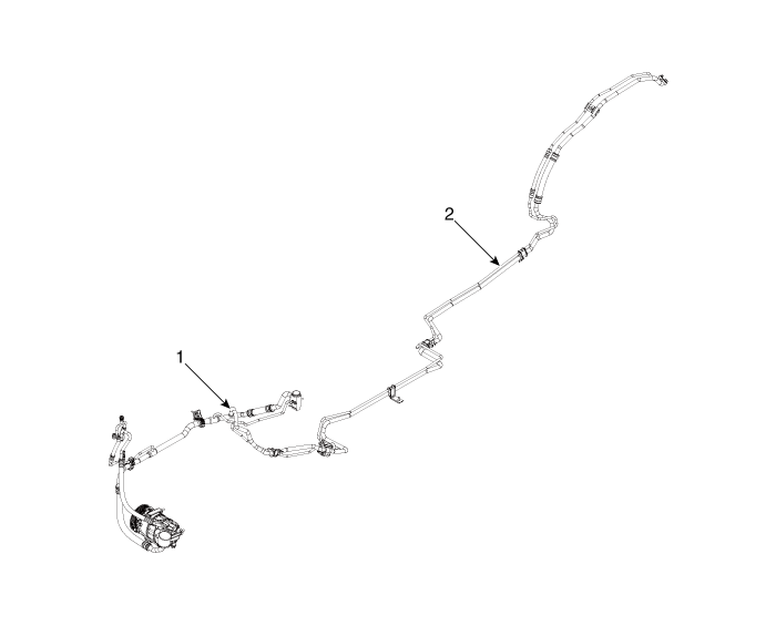
1. Front Suction
& Liquid Pipe Assembly
|
2. Rear Suction
& Liquid Pipe Assembly
|
Refrigerant Line. Repair procedures
[Front suction & Liquid pipe assembly]
|
1. |
If a compressor is available, the air conditioner is operated for a
few minutes in the engine idle state and then the engine is stopped.
|
|
2. |
Disconnect the negative (-) battery terminal.
|
|
3. |
Recover the refrigerant with a recovery/charging station.
|
|
4. |
Remove the engine cover.
(Refer to Engine Mechanical System - "Engine Cover")
|
|
5. |
Loosen the mounting bolts and separate the expansion valve (A) fron
evaporator core.
|
Tightening torque :
8.8 - 13.7 N.m (0.9 - 1.4 kgf.m, 6.5 - 10.1 lb-ft)
|
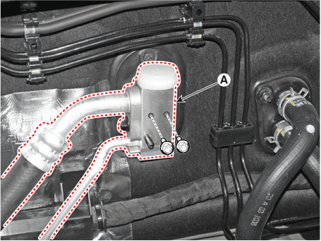
|
|
6. |
Loosen the mounting nuts and separate the suction line (A), discharge
line (B).
|
Tightening torque :
19.6 - 23.5 N.m (2.0 - 2.4 kgf.m, 14.5 - 17.4 lb-ft)
|
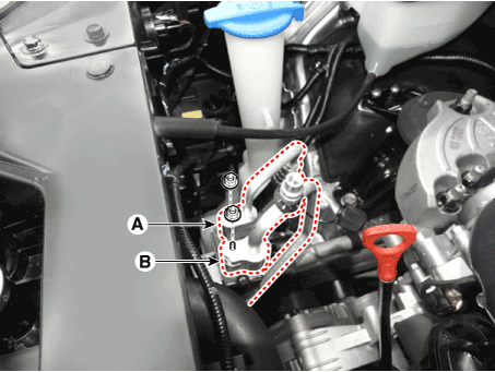
|
|
7. |
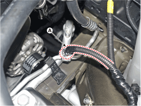
Press the lock pin and separate the APT sensor connector (A).
|
|
8. |
Remove the engine room under cover.
(Refer to Engine Mechanical System - "Engine Room Under Cover")
|
|
9. |
Remove the engine mounting braket.
(Refer to Engine Mechanical System - "Engine Mounting")
|
|
10. |
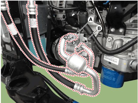
Separate the compressor suction line (A) and discharge line (B) connection
nuts and disconnect the line.
|
Tightening torque :
19.6 - 23.5 N.m (2.0 - 2.4 kgf.m, 14.5 - 17.4 lb-ft)
|
|
• |
Be careful not to damage the parts located under the
vehicle (floor under cover, fuel filter, fuel tank and
canister) when raising the vehicle using the lift.
(Refer to General Information - "Lift and Support Points")
|
|
|
|
11. |
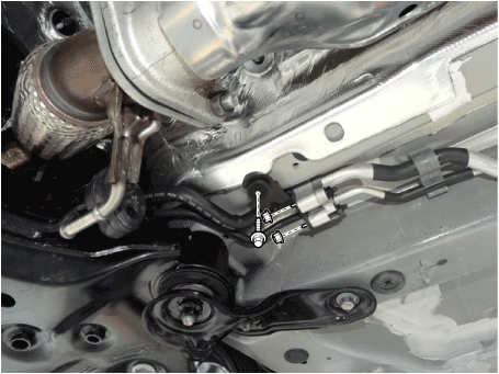
Remove the refrigerant pipe line mounting nuts and braket bolt.
|
Tightening torque
Nut : 8.8 - 13.7 N.m (0.9 - 1.4 kgf.m, 6.5 - 10.1 lb-ft)
Bolt : 7.8 - 11.8 N.m (0.8 - 1.2 kgf.m, 5.8 - 8.7 lb-ft)
|
|
|
12. |
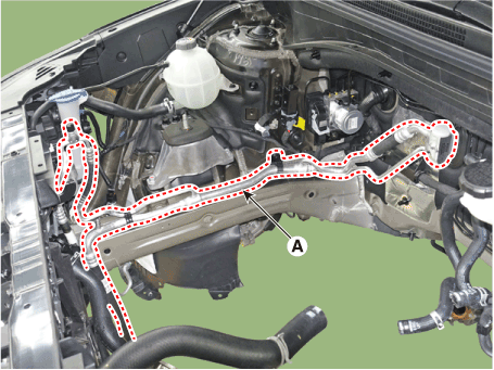
Loosen the mounting bolt and remove the Front suction & Liquid pipe
assembly (A).
|
Tightening torque :
7.8 - 11.8 N.m (0.8 - 1.2 kgf.m, 5.8 - 8.7 lb-ft)
|
|
|
13. |
Install in the reverse order of removal.
|
• |
Plug or cap the lines immediately after disconnecting
them to avoid moisture and dust contamination.
|
|
• |
Tighten the bolt or nut joint to the specified torque.
|
|
• |
Using a gas leak detector, check for refrigerant leakage.
|
|
• |
Evacuate air in the refrigeration system and charge
system with refrigerant.
|
Capacity :
R-134a (Single) : 650 ± 25g (20.9 ± 0.88oz)
R-134a (Dual) : 850 ± 25g (29.9 ± 0.88oz)
R-1234yf (Single) : 625 ± 25g (22.0 ± 0.88oz)
R-1234yf (Dual) : 800 ± 25g (28.2 ± 0.88oz)
|
|
|
|
[Refrigerant Line (Condenser)]
|
1. |
Remove the front bumper assembly.
(Refer to Body (Interior and Exterior) - "Front Bumper Assembly")
|
|
2. |
Recover the refrigerant with a recovery/charging station.
|
|
3. |
Loosen the mounting nuts and separate the suction line (A), discharge
line (B).
|
Tightening torque :
19.6 - 23.5 N.m (2.0 - 2.4 kgf.m, 14.5 - 17.4 lb-ft)
|

|
|
4. |
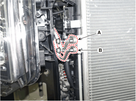
Loosen the mounting nuts, and then disconnect the discharge line (A)
and liquid line (B) from the condenser.
|
Tightening torque :
19.6 - 23.5 N.m (2.0 - 2.4 kgf.m, 14.5 - 17.4 lb-ft)
|
|
|
5. |
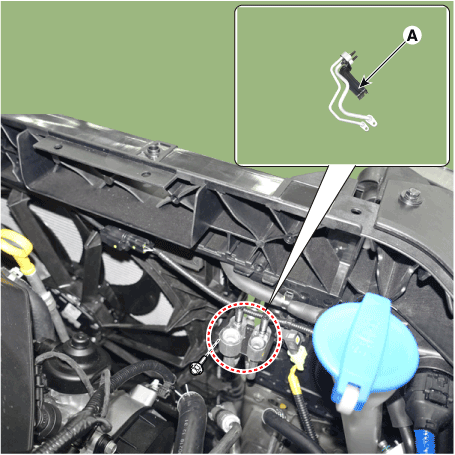
Loosen the mounting bolt, remove the refrigerant line (Condenser) (A).
|
Tightening torque :
7.8 - 11.8 N.m (0.8 - 1.2 kgf.m, 5.8 - 8.7 lb-ft)
|
|
|
6. |
Install in the reverse order of removal.
|
• |
Plug or cap the lines immediately after disconnecting
them to avoid moisture and dust contamination.
|
|
• |
Tighten the bolt or nut joint to the specified torque.
|
|
• |
Using a gas leak detector, check for refrigerant leakage.
|
|
• |
Evacuate air in the refrigeration system and charge
system with refrigerant.
|
Capacity :
R-134a (Single) : 650 ± 25g (20.9 ± 0.88oz)
R-134a (Dual) : 850 ± 25g (29.9 ± 0.88oz)
R-1234yf (Single) : 625 ± 25g (22.0 ± 0.88oz)
R-1234yf (Dual) : 800 ± 25g (28.2 ± 0.88oz)
|
|
|
|
[Rear Suction & Liquid Pipe Assembly]
|
1. |
If a compressor is available, the air conditioner is operated for a
few minutes in the engine idle state and then the engine is stopped.
|
|
2. |
Disconnect the negative (-) battery terminal.
|
|
3. |
Recover the refrigerant with a recovery/charging station.
|
|
4. |
Remove the rear wheel guard [RH].
(Refer to Body - "Rear Wheel Guard")
|
|
5. |
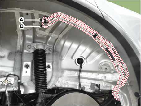
Loosen the mounting nuts and separate the suction line (A), discharge
line (B).
|
Tightening torque :
19.6 - 23.5 N.m (2.0 - 2.4 kgf.m, 14.5 - 17.4 lb-ft)
|
|
|
6. |
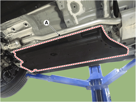
Loosen the mounting bolts , nuts and remove the engine roon under cover[RH].
|
Tightening torque :
8.8 - 13.7 N.m(0.9 - 1.4 kgf.m, 6.5 - 10.1 lb-ft)
|
|
|
7. |
Remove the refrigerant pipe line mounting nuts.
|
Tightening torque :
7.8 - 11.8 N.m (0.8 - 1.2 kgf.m, 5.8 - 8.7 lb-ft)
|
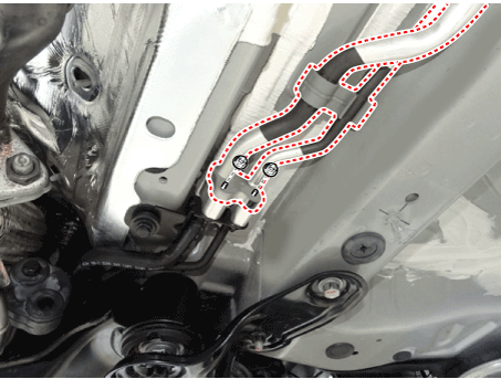
|
|
8. |
Loosen the mounting bolt and remove the Rear suction & Liquid pipe assembly
(A).
|
Tightening torque :
7.8 - 11.8 N.m (0.8 - 1.2 kgf.m, 5.8 - 8.7 lb-ft)
|
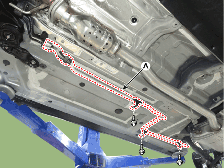
|
|
9. |
Install in the reverse order of removal.
|
• |
Plug or cap the lines immediately after disconnecting
them to avoid moisture and dust contamination.
|
|
• |
Tighten the bolt or nut joint to the specified torque.
|
|
• |
Using a gas leak detector, check for refrigerant leakage.
|
|
• |
Evacuate air in the refrigeration system and charge
system with refrigerant.
|
Capacity :
R-134a (Single) : 650 ± 25g (20.9 ± 0.88oz)
R-134a (Dual) : 850 ± 25g (29.9 ± 0.88oz)
R-1234yf (Single) : 625 ± 25g (22.0 ± 0.88oz)
R-1234yf (Dual) : 800 ± 25g (28.2 ± 0.88oz)
|
|
|
|
Compressor. Description and operation
The compressor is the power unit of the A/C system.
It is located on the side of engine block and driven by a V-belt of the engine.
The compressor changes low pressure and low temperature refrigerant gas into
high pressure and high temperature refrigerant gas.
Variable Swash Plate Compressor
The compressor has a swash plate that rotates to reciprocate pistons, which
compress refrigerant.
The variable swash plate compressor controls the swash plate angle to change
the refrigerant displacement. It achieves precise cooling capability control
in accordance with vehicle interior and driving conditions.
The internally controlled variable swash plate compressor changes the swash
plate angle by a MCV (Mechanical Control Valve) in accordance with fluctuation
of a suction pressure.
The externally controlled variable swash plate compressor changes the swash
plate angle by an ECV (Electric Control Valve) in accordance with an electrical
signal from the heater & A/C control unit.
This enables stable temperature control and improved driving sensation.
ECV Control Diagram
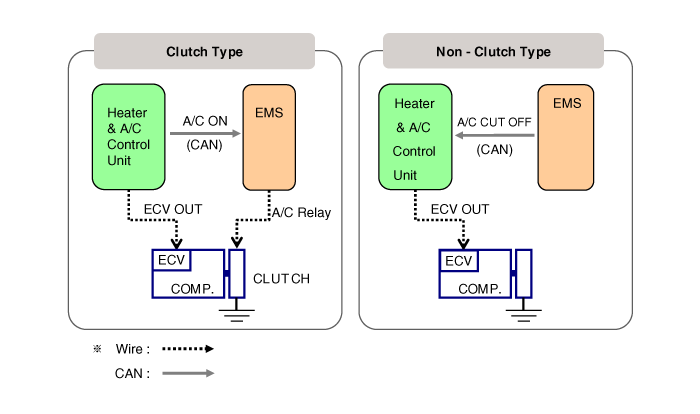
Compressor. Components and components location
[Diesel 2.2 TCI-R]
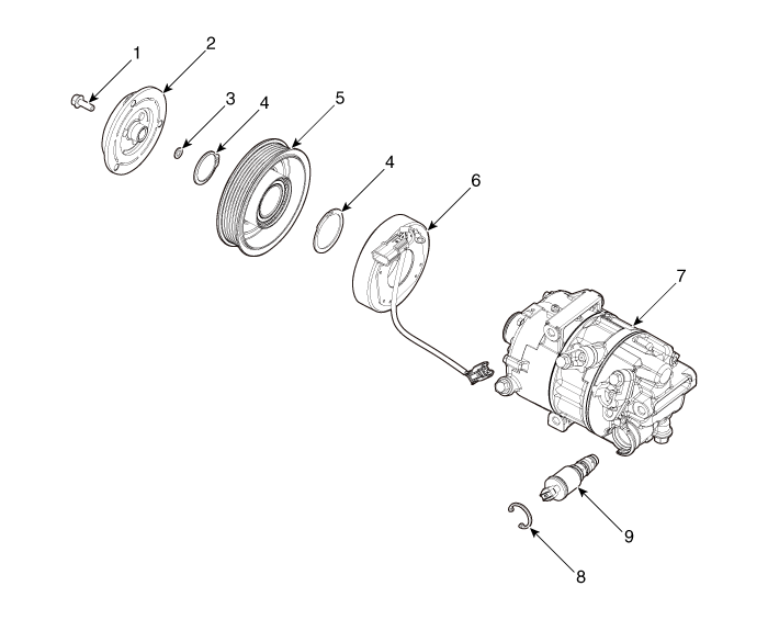
1. Clutch Bolt
2. Disc & Hub Assembly
3. Clutch Spacer
4. Snap Ring
5. Pulley
|
6. Magnetic Coil
Assembly
7. Compressor
8. Electric Control Valve (ECV) spacer
9. Electric Control Valve (ECV)
|
[Except Diesel 2.2 TCI-R]
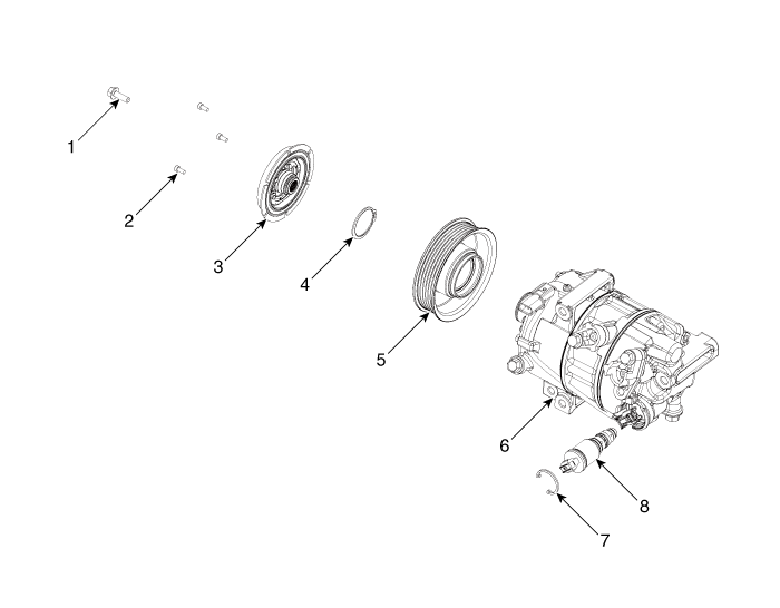
1. Clutch Bolt
2. Limiter Bolt
3. Limiter & Damper Assembly
4. Snap Ring
|
5. Pulley
6. Compressor
7. Electric Control Valve (ECV) spacer
8. Electric Control Valve (ECV)
|
Compressor. Repair procedures
|
1. |
If a compressor is available, the air conditioner is operated for a
few minutes in the engine idle state and then the engine is stopped.
|
|
2. |
Disconnect the negative (-) battery terminal.
|
|
3. |
Recover the refrigerant with a recovery/charging station.
|
|
4. |
Loosen the drive belt.
(Refer to Engine Mechanical System - "Drive Belt")
|
|
5. |
Loosen the mounting nuts and separate the suction line (A), discharge
line (B).
|
Tightening torque :
19.6 - 23.5 N.m (2.0 - 2.4 kgf.m, 14.5 - 17.4 lb-ft)
|
|
• |
Plug or cap the lines immediately after disconnecting
them to avoid moisture and dust contamination.
|

|
|
|
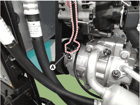
6. |
Press the lock pin and separate the ECV connector (A).
|
|
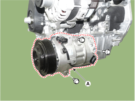
7. |
Loosen the mounting bolts and remove the compressor assembly (A).
|
Tightening torque :
19.6 - 23.5 N.m (2.0 - 2.4 kgf.m, 14.5 - 17.4 lb-ft)
|
|
|
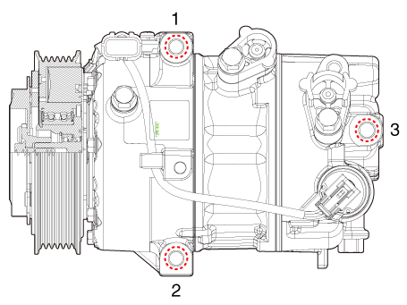
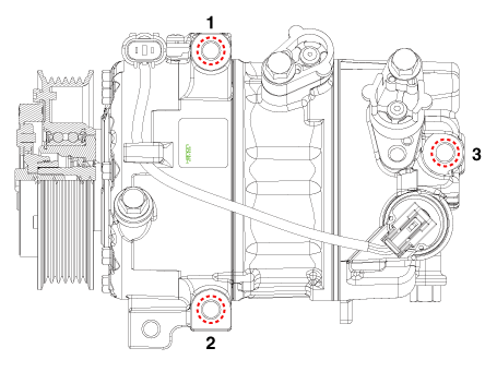
1. |
Make sure that the compressor (A) mounting bolt of the correct length
is screwed in. Tighten the mounting bolts in the specified tightening
order.
|
Tightening torque :
19.6 - 23.5 N.m (2.0 - 2.4 kgf.m, 14.5 - 17.4 lb-ft)
|
[Diesel 2.2 TCI-R]
[Execpt Diesel 2.2 TCI-RI]
|
|
2. |
Install in the reverse order of removal.
| •
|
If you install a new compressor, drain all the refrigerant oil
from the removed compressor and measure its volume. Subtract
the volume of drained oil from the original capacity. The result
is the amount of oilcompressor oil you should drain from the
new compressor (through the suction fitting).
|
| •
|
Replace the O-rings with new ones at each fitting, and apply
a thin coat of refrigerant oil before installing them. Be sure
to use the right O-rings for R-134a, R-1234yf to avoid leakage.
|
| •
|
To avoid contamination, do not return the oil to the container
once dispensed, and never mix it with other refrigerant oils.
|
| •
|
Immediately after using the oil, replace the cap on the container
and seal it to avoid moisture absorption.
|
|
|
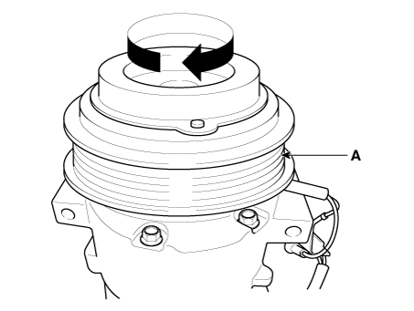
1. |
Check the pulley (A) bearing play and drag by rotating the pulley by
hand. Replace the pulley with a new one if it is noisy or has excessive
play/drag.
|
| External Control Valve Compressor Inspection
(GDS) |
Compressor type: Fixed type compressor, External control valve, Internal control
valve.
In cases of fixed type and internal control valve, it is possible to inspect
compressor's operation with clutch noise.
When it comes to External control valve, however, it cannot be checked in this
way bacause it doesn't have a clutch.
So, ECV should be inspected with GDS as below.
|
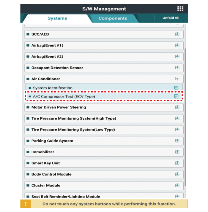
1. |
Connect GDS to the vehicle and select 'Aircon Compressor Test(ECV type)'
[ECV1]
|
|
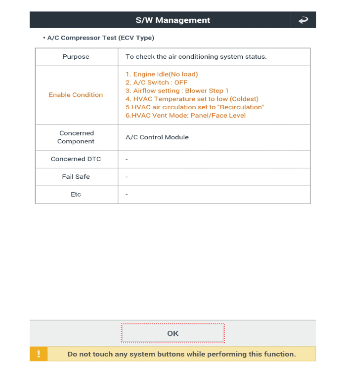
2. |
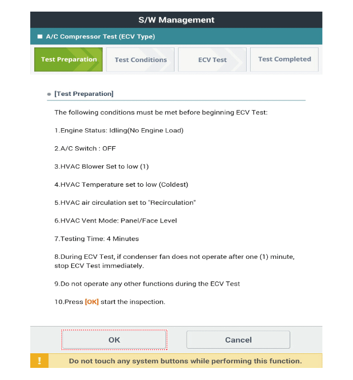
Make the vehicle ready as the GDS instruction on the monitor. (Turn
off A/C 'switch' only)
|
|
3. |
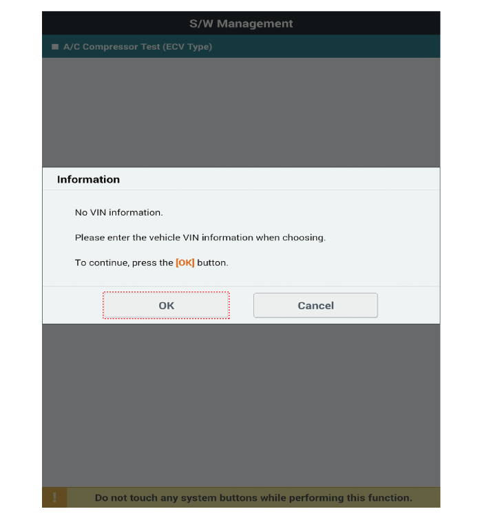
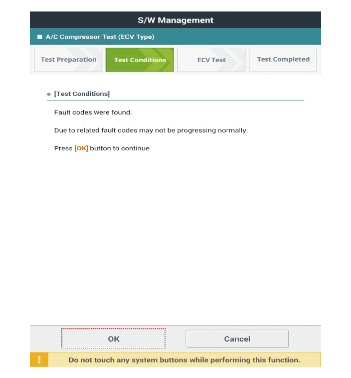
Check if other DTC codes are found before inspect ECV compressor. If
so, solve that problems first. If not, press 'OK' button to continue.
|
Do not continue inspection if these DTC codes are found: B1241,
B1242, B1672, B1685, B1686, B1687
|
|
|
4. |
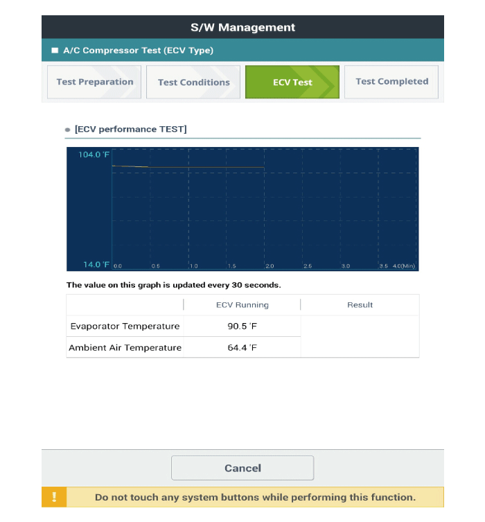
Start inspection
|
Check if condenser fan is operating when condition is changed
to 'ECV running'
|
|
Relief valve will operate if condenser fandoesn't work due to
overpressure in thecompressor. It helps the airconditiong system
torelieve by releasing refrigerant and oil (losed ifrelieved).
※ Refill refrigerant and oil after operation of relief valve
※ Noise occurred when relief valve is in operation
|
|
|
5. |
Check the result of inspection.
[ECV7]
[ECV8]
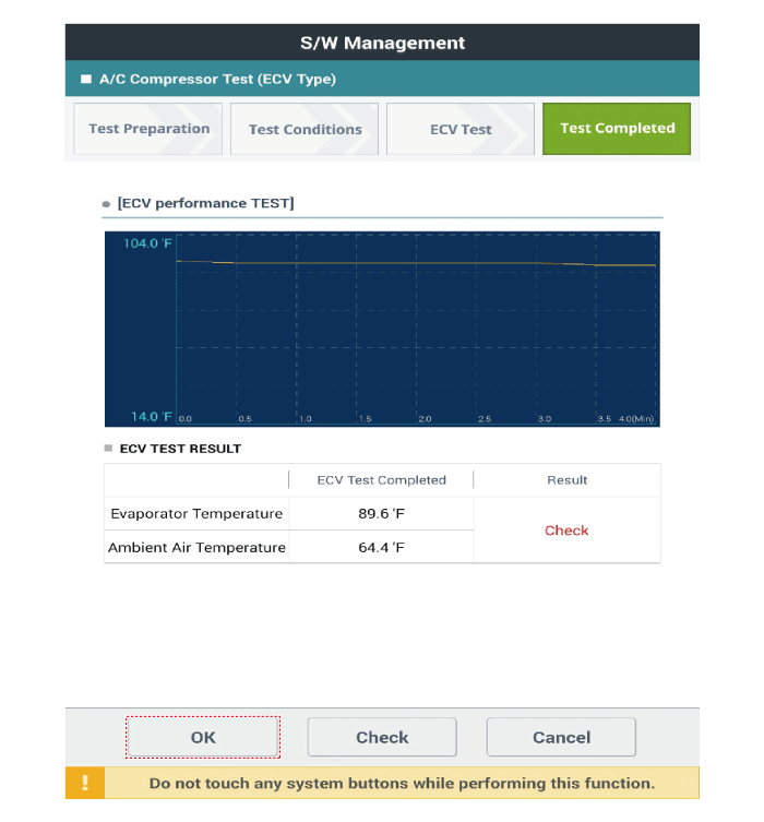
|
|
6. |
If the result shows "Check" , click "Check" and follow the instruction.
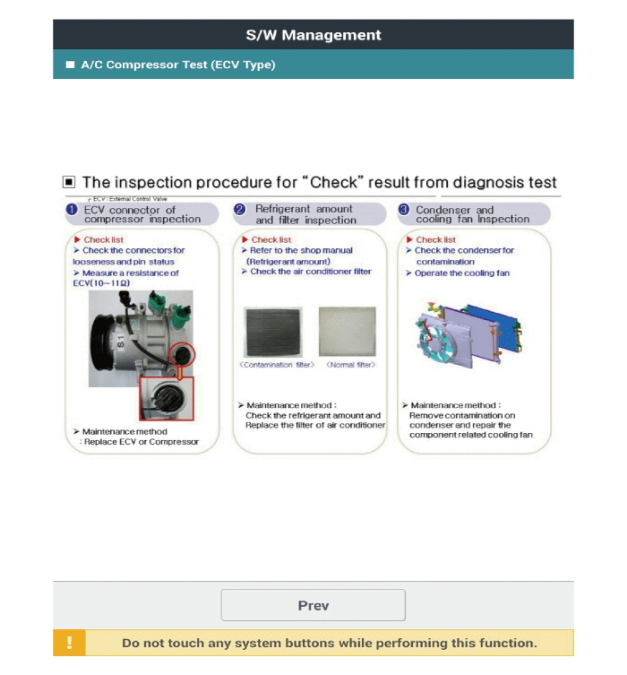
|
|
7. |
Inspect ECV again from the first step.
|
|
1. |
Remove the front tire [RH].
|
|
2. |
Loosen the drive belt.
(Refer to Engine Mechanical System - "Drive Belt")
|
|
3. |
Remove the clutch bolt (A) while holding the pulley with a clutch bolt
remover (09977-3R000).
|
Tightening torque :
15.0 - 21.0 N.m (1.53 - 2.14 kgf.m , 11.1 - 15.5 lb - ft)
|
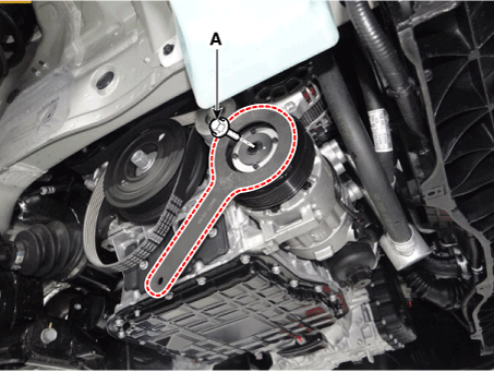
|
|
4. |
Loossen the limiter bolts and then remove the limiter & hub assembly.
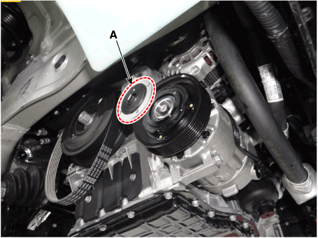
|
|
5. |
Remove the pulley (B) after removing the snap ring (A) with a snap ring
plier.
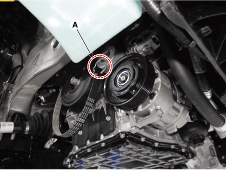
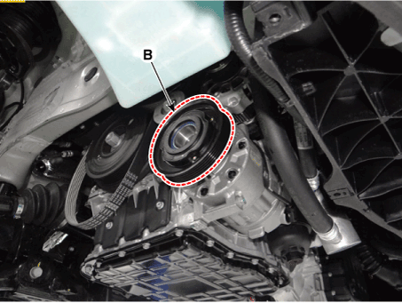
|
• |
Be careful not to damage the pulley and compressor during
disassembly/reassembly.
|
|
• |
Once the snap ring is removed, replace it with a new
one.
|
|
|
|
6. |
Reassemble in the reverse order of disassembly.
|
• |
Clean the pulley and compressor sliding surfaces with
non-petroleum solvent.
|
|
• |
Install a new snap ring, and make sure they are fully
seated in the groove.
|
|
• |
Make sure that the pulley turns smoothly after reassembly.
|
|
|
Condenser. Components and components location
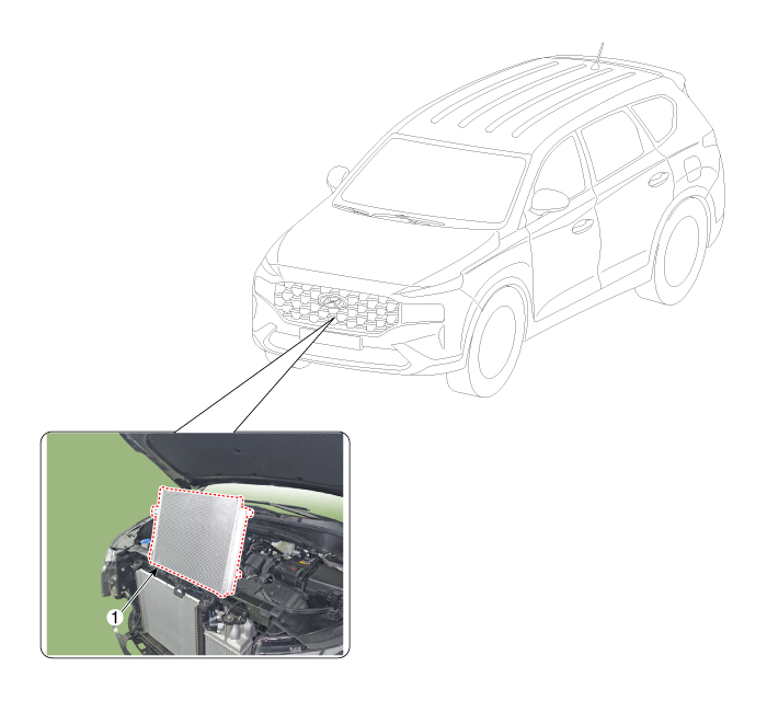
Condenser. Repair procedures
|
1. |
Check the condenser fins for clogging and damage. If clogged, clean
them with water, and blow them with compressed air. If bent, gently
bend them using a screwdriver or pliers.
|
|
2. |
Check the condenser connections for leakage, and repair or replace it,
if required.
|
|
1. |
Recover the refrigerant with a recovery/recycling/charging station.
|
|
2. |
Disconnect the negative (-) battery terminal.
|
|
3. |
Remove the front bumper.
(Refer to Body - "Front Bumper Assembly")
|
|
4. |
Remove the hood latch assembly.
(Refer to Body - "Hood Latch Assembly")
|
|
5. |
Loosen the mounting bolts, remove the air duct (A).
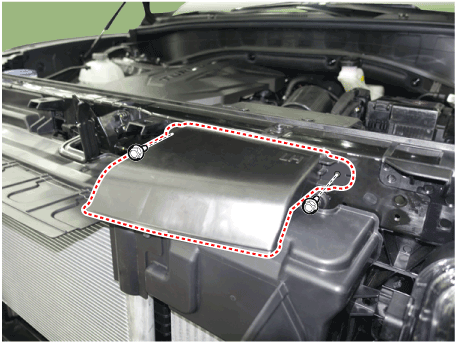
|
|
6. |
Loosen the mounting bolts and nuts, remove the front bumper beam assembly
(A).
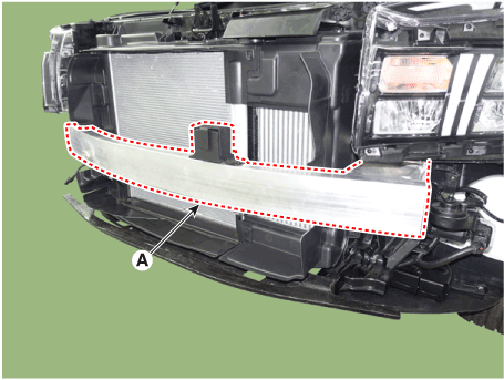
|
|
7. |
Loosen the mounting bolts and screws , remove the upper air guard (A).
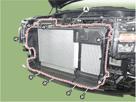
|
|
8. |
Loosen the mounting nuts and separate the discharge line (A) and liquid
line (B).

|
|
9. |
Press the lock pin and remove the condenser assembly (A) from radiator
assembly.
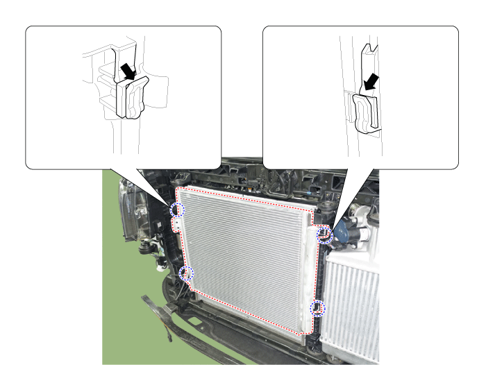
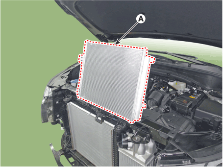
|
|
10. |
Install in the reverse order of removal.
|
• |
If you're installing a new condenser, add refrigerant
oil.
|
|
• |
Replace the O-rings with new ones at each fitting, and
apply a thin coat of refrigerant oil before installing
them. Be sure to use the right O-rings for R-134a or
R-1234yf to avoid leakage.
|
|
• |
Be careful not to damage the radiator and condenser
fins when installing the condenser.
|
|
• |
Charge the system, and test its performance.
|
|
|
Receiver-Drier. Repair procedures
|
1. |
Using a Lwrench, remove the cap (A) on the bottom of the receiver-drier.
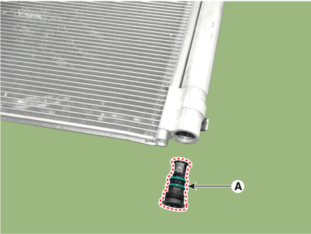
|
|
2. |
Remove the receiver-drier (A) from condenser using a long nose plier.
Check for crumbled receiver-drier and clogged bottom cap filter.
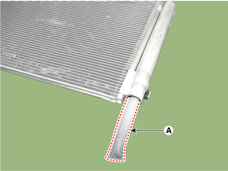
|
|
3. |
Install in the reverse order of removal.
|
• |
Always replace the receiver-drier and bottom cap at
the same time.
|
|
• |
Replace the O-rings with new ones at each fitting, and
apply a thin coat of refrigerant oil before installing
them. Be sure to use the right O-rings for R-134a or
R-1234yf to avoid leakage.
|
|
• |
Be careful not to damage the radiator and condenser
fins when installing the condenser.
|
|
• |
Charge the system, and test its performance.
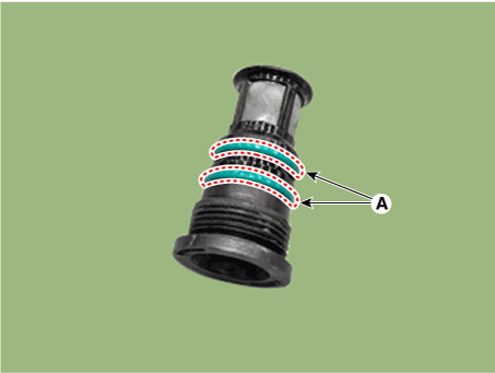
|
|
|
A/C Pressure Transducer. Description and operation
The A/C Pressure Transducer (APT) converts the pressure value of high pressure
line into voltage value after measuring it. By converted voltage value, engine
ECU controls the cooling fan by operating it high speed or low speed. Engine
ECU stops the operation of the compressor when the temperature of refrigerant
line is very high or very low irregularly to optimize air conditioning system.
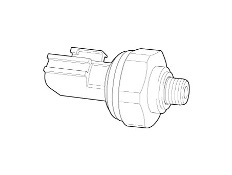
A/C Pressure Transducer. Repair procedures
| •
|
Before measuring the pressure of the refriferant line, check
whether the refrigerant amount is charged in accordance with
the specified charging amount.
(Refer to Heating, Ventilation, Air Conditioning - "Specifications")
|
|
|
1. |
Turn the ignition switch OFF.
|
|
2. |
Install the refrigerant recovery/recycling/charging system.
(Refer to Air Conditioning System - "Repair procedures")
|
|
3. |
Turn ON the ignition switch, put into operation the air conditioner.
|
|
4. |
Calculate the reference voltage of the Recovery/Recycle/Recharge machine
high pressure value using the formula below.
|
Reference voltage (V) = 0.0088 * pressure(psi) + 0.37
|
|
|
5. |
Measure the sensor output voltage between terminal "1" and "2".
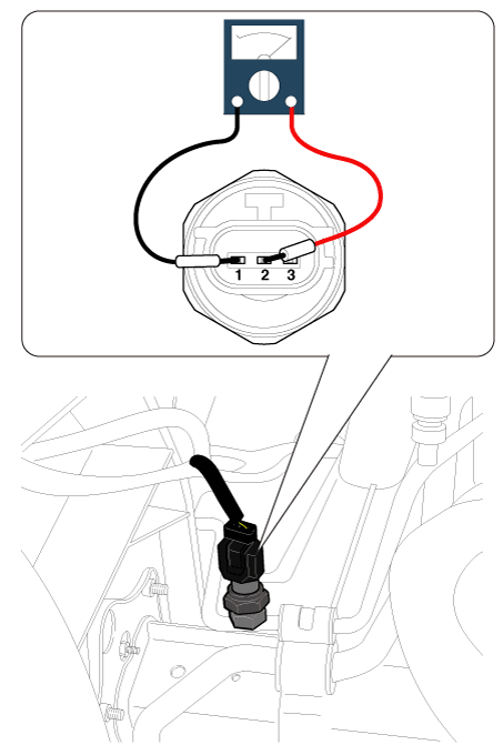
Pin No
|
Function
|
1
|
Ground
|
2
|
Voltage
|
3
|
Power (+5V)
|
|
|
6. |
If the reference voltage value and the sensor output voltage value are
close to each other, the air conditioner pressure transducer is normal.
|
|
7. |
If 0V is output or the reference voltage value and sensor output voltage
value are not close to each other, replace the air conditioner pressure
transducer.
|
• |
Check if the output voltage changes when the high pressure
value of the refrigerant line changes.
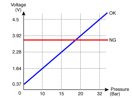
|
|
|
|
1. |
Disconnect the negative (-) battery terminal.
|
|
2. |
Recover the refrigerant with a recovery/charging station.
|
|
3. |
Disconnect the A/C pressure transducer connector (A).

|
|
4. |
Remove the A/C pressure transducer (A).
|
Tightening torque :
10 - 12 N.m (1.02 - 1.22 kgf.m, 7.4 - 8.8 lb-ft)
|
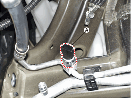
|
• |
Be careful not to bend the liquid & suction pipe.
|
|
|
|
5. |
Install in the reverse order of removal.
|
• |
When installing, replace it with a new O-ring (A).
|
|
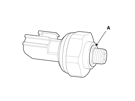
|
Evaporator Temperature Sensor. Description and operation
The evaporator temperature sensor will detect the evaporator core temperature
and interrupt compressor relay power in order to prevent evaporator from freezing
by excessive cooling.
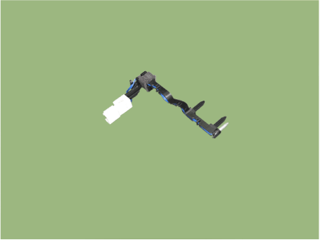
Evaporator Temperature Sensor. Repair procedures
|
1. |
Turn the ignition switch OFF.
|
|
2. |
Disconnect the evaporator temperature sensor connector.
|
|
3. |
Measure resistance between terminal "+" and "-" of the evaporator temperature
sensor.
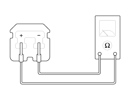
Specification
Temperature[°C(°F)]
|
Min. Resistance[kΩ]
|
Resistance[kΩ]
|
Max. Resistance[kΩ]
|
-2 (28.4)
|
28.84
|
30.16
|
30.48
|
0 (32)
|
27.35
|
27.62
|
29.89
|
2 (35.6)
|
25.05
|
25.32
|
25.59
|
4 (39.2)
|
22.97
|
23.24
|
23.51
|
6 (42.8)
|
21.08
|
21.35
|
21.61
|
|
|
4. |
Connect the evaporator temperature sensor connector.
|
|
5. |
Run the engine and turn the A/C switch ON, then measure the voltage
between the terminals of the harness connector.
|
|
1. |
Disconnect the negative (-) battery terminal.
|
|
2. |
Remove the evaporator core.
(Refer to Heater - "Evaporator Core")
|
|
3. |
Separate the evaporator temperature sensor (A) from the evaporator core.
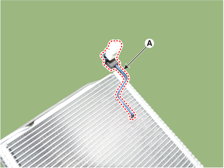
|
|
4. |
Install in the reverse order of removal.
|
In-car Sensor. Description and operation
The In-car air temperature sensor is built in the heater & A/C control unit.
The sensor consists of a thermistor that measures the inside temperature. The
signal decided by the resistance value that changes in accordance with perceived
inside temperature, is delivered to heater control unit, and according to this
signal, the control unit regulates in-car temperature to intended value.
Photo Sensor. Description and operation
The photo sensor is located at the center of the defrost nozzles.
The photo sensor contains a photovoltaic (sensitive to sunlight) diode. The
solar radiation received by its light receiving portion, generates an electromotive
force in proportion to the amount of radiation received which is transferred
to the automatic temperature control module so that the solar radiation compensation
will be performed.
Photo Sensor. Repair procedures
|
1. |
Emit intensive light toward the photo sensor using a lamp, and check
the output voltage change.
|
|
2. |
The voltage will rise with higher intensive light and reduce with lower
intensive light.
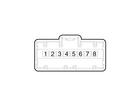
1. Auto
light signal
2. Auto light ground
3. Photo signal (RH)
4. LED power (B+)
|
5. LED
ground (To BCM)
6. Photo signal (LH)
7. Photo power (SW)
8. Auto light power (5V)
|
|
|
1. |
Disconnect the negative (-) battery terminal.
|
|
2. |
Using a screwdriver or remover, remove the photo sensor (A).
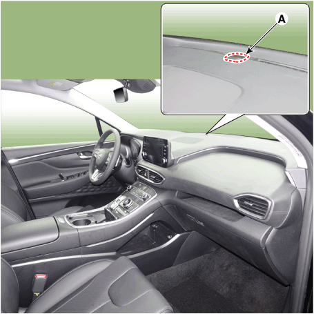
|
|
3. |
Press the lock pin, separate the photo sensor connector (A).
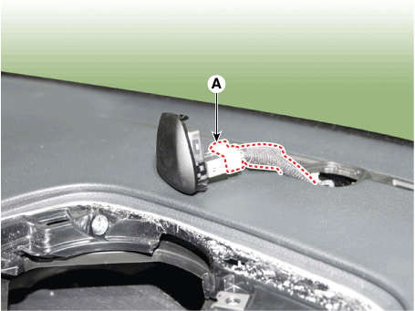
|
|
4. |
Install in the reverse order of removal.
|
Ambient Temperature Sensor. Description and operation
The ambient temperature sensor is located at the front of the condenser and
detects ambient air temperature. It is a negative type thermistor; resistance
will increase with lower temperature, and decrease with higher temperature.
The sensor output will be used for discharge temperature control, temperature
regulation door control, blower motor level control, mix mode control and in-car
humidity control.
| •
|
If the ambient temperature is below 1.0°C (33.8°F), the A/C
compressor will stop.
|
| •
|
The compressor will operate manually.
|
|
Ambient Temperature Sensor. Repair procedures
|
1. |
Check the resistance of the ambient temperature sensor between terminals
1 and 2 whether it changes by changing the ambient temperature.
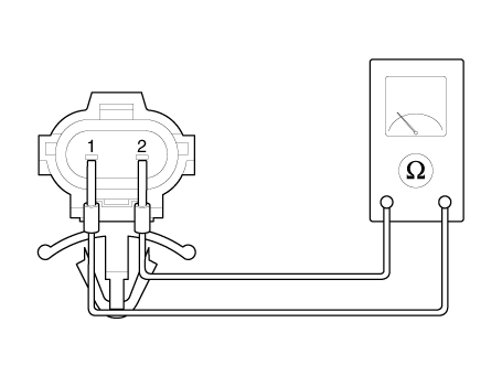
1. Ambient
Sensor (+)
|
2. Sensor
ground
|
Specification
Ambient temperature [°C (°F)]
|
Resistance between terminals 1 and 2 (kΩ ± 3%)
|
-30 (-22)
|
480.41
|
-20 (-4)
|
271.21
|
-10 (14)
|
158.18
|
0 (32)
|
95.1
|
10 (50)
|
58.8
|
20 (68)
|
37.32
|
30 (86)
|
24.26
|
40 (104)
|
16.13
|
50 (122)
|
10.95
|
|
|
2. |
If the measured resistance is not within specification, substitute with
a known-good ambient temperature sensor and check for proper operation.
|
|
3. |
Replace the ambient temperature sensor if it is proved that there is
a problem with the sensor.
|
|
1. |
Disconnect the negative (-) battery terminal.
|
|
2. |
Remove the front bumper.
(Refer to Body - "Front Bumper Assembly")
|
|
3. |
Disconnect the connector (A) and then remove the ambient temperature
sensor (B).
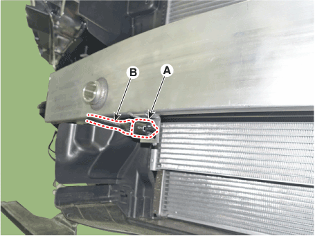
|
|
4. |
Install in the reverse order of removal.
|
Auto Defogging Sensor. Description and operation
The auto defogging sensor is installed on the front window glass. The sensor
judges and sends signal if moisture occurs to blow out wind for defogging. The
air conditioner control module receives signal from the sensor and restrains
moisture and eliminate defog by controlling the intake actuator, A/C, auto defogging
actuator, blower motor rpm, and mode actuator.
Auto Defogging Sensor. Repair procedures
To inspect and diagnose the sensor, refer to Self-Diagnosis procedure and DTC
guide.
|
1. |
Disconnect the negative (-) battery terminal.
|
|
2. |
Remove the rain sensor inner cover (A) and rain sensor cover (B).
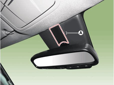
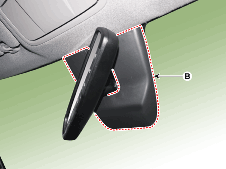
|
|
3. |
Separate the auto defogging sensor connector (A) and remove the auto
defogging sensor (A).
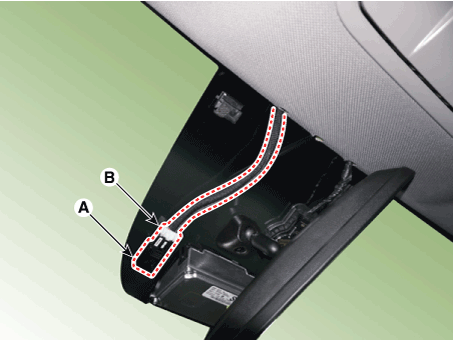
|
|
4. |
Install in the reverse order of removal.
|
Special Tools Tool (Number and name) Illustration Use 09977-3R000 Clutch bolt remover Removal and installation of clutch bolt ...
Heater Unit. Components and components location Component Location 1. Heater Unit Assembly Components 1. Heater unit assembly 2. Heater NVH pad 3. Heater seal duct 4. Heater tube cover 5. Heater core assembly ...
See also:
Immobilizer System
Description and operation Description The immobilizer system will disable the vehicle unless the proper ignition key is used, in addition to the currently available anti-theft systems such as car alarms, ...
Seat warmer (for rear seat)
The seat warmer is provided to warm the rear seats during cold weather. With the ignition switch in the ON position, push either of the switches to warm rear seats. During mild weather or under conditions ...
Parking brake
Applying the parking brake Foot type To engage the parking brake, first apply the foot brake and then depress the parking brake pedal down as far as possible. CAUTION Driving with the parking brake applied ...
 Hyundai Santa Fe (TM): Air conditioning System


 Special service tools
 Heater


