 Hyundai Santa Fe (TM): Heater
Heater Unit. Components and components location
| Component Location |
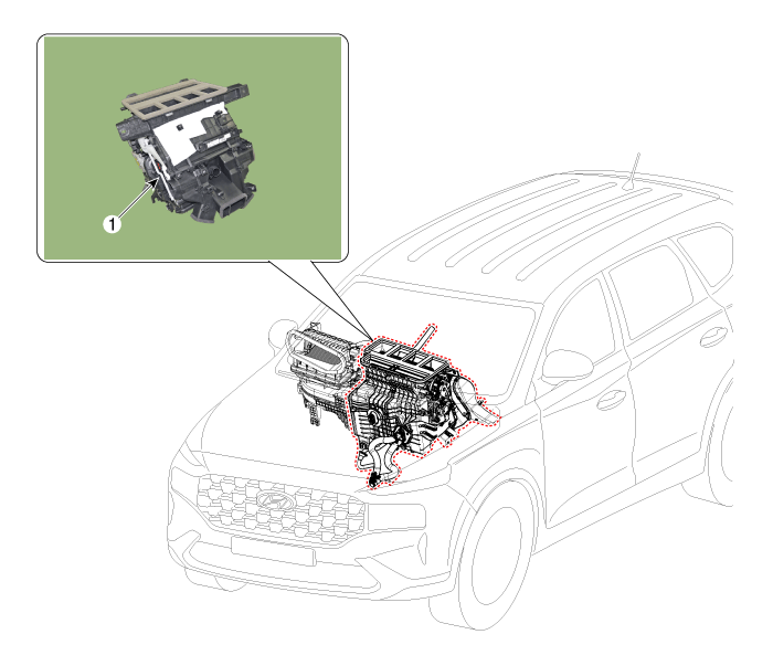
| 1. Heater Unit
Assembly |
| Components |
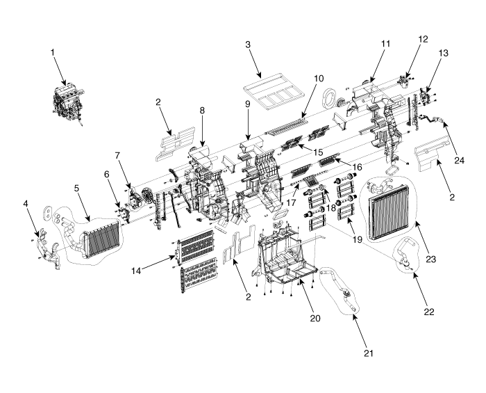
| 1. Heater
unit assembly 2. Heater NVH pad 3. Heater seal duct 4. Heater tube cover 5. Heater core assembly 6. Tempearture control actuator (Single) 7. Mode control actuator 8. Heater case [LH] |
9. Heater
divider plate 10. DEF door assembly 11. Heater case [RH] 12. Auto defogging actuator 13. Temperature control actuator (Dual) 14. PTC heater 15. VENT door assembly 16. Floor door assembly |
17. Mode
door assembly 18. Temperature door shaft 19. Temperature door assembly 20. Heater drain fan 21. Drain hose assembly 22. Aspirator hose 23. Evaporator core assembly 24. Evaporator temperature sensor |
Heater Unit. Repair procedures
| Replacement |
| 1. |
Disconnect the negative (-) battery terminal.
|
| 2. |
Recover the refrigerant with a recovery/recycling/charging station.
|
| 3. |
When the engine is cool, drain the engine coolant from the radiator.
(Refer to Engine Mechanical System - "Coolant")
|
| 4. |
Remove the cowl top cover.
(Refer to Body - "Cowl Top Cover")
|
| 5. |
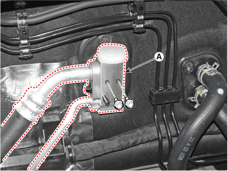
Loosen the mounting bolts and separate the expension valve (A) from
the evaporator core.
|
| 6. |
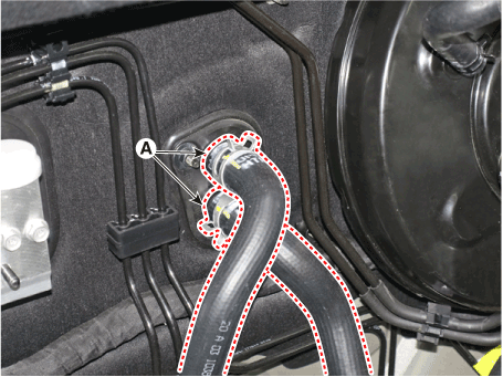
Separate the heater hose (A).
|
| 7. |
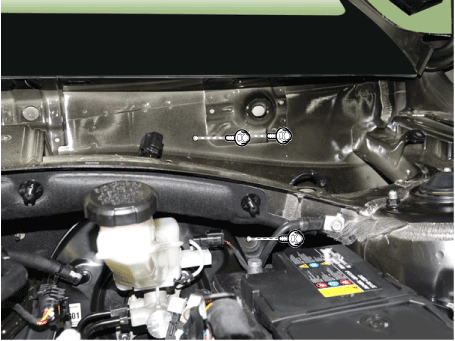
Loosen the cowl cross bar assembly mounting bolts.
|
| 8. |
Remove the front seat assembly.
(Refer to Body - "Front Seat Assembly")
|
| 9. |
Remove the floor console assembly.
(Refer to Body - "Floor Console Assembly")
|
| 10. |
Remove the front pillar trim.
(Refer to Body - "Front Pillar Trim")
|
| 11. |
Remove the cowl side trim.
(Refer to Body - "Cowl Side Trim")
|
| 12. |
Remove the crash pad lower panel.
(Refer to Body - "Crash Pad Lower Panel")
|
| 13. |
Remove the steering column shroud panel.
(Refer to Body - "Steering Column Shroud Panel")
|
| 14. |
Remove the steering wheel.
(Refer to Steering System - "Steering Wheel")
|
| 15. |
Remove the multifunction switch.
(Refer to Body Electrical System - "Multifunction Switch")
|
| 16. |
Lower the steering column after loosening the mounting bolts.
(Refer to Steering System - "Steering Column and Shaft")
|
| 17. |
Remove the front door scuff trim.
(Refer to Body - "Door Scuff Trim")
|
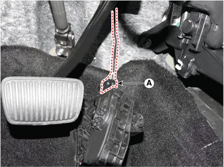
| 18. |
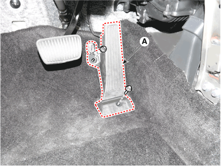
Loosen the mounting bolt and nut, remove the accelerator pedal module
(A).
|
| 19. |
Press the lock pin, separate the accelerator pedal connector (A).
|
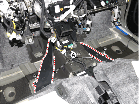
| 20. |
Remove the rear air duct (A) and then separate the floor carpet (B)
backwards.
|
| 21. |
Loosen the mounting nuts and remove the rear heating duct (A).
|
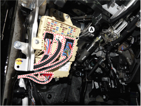
| 22. |
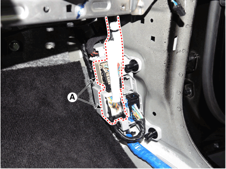
Disconnect the junction box connectors (A).
|
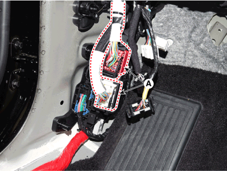
| 23. |
Disconnect the multi box connectors (A).
[Driver]
[Passenger]
|
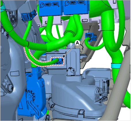
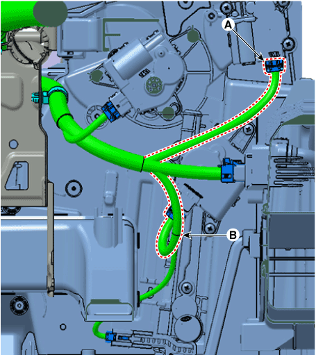
| 24. |
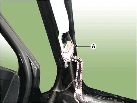
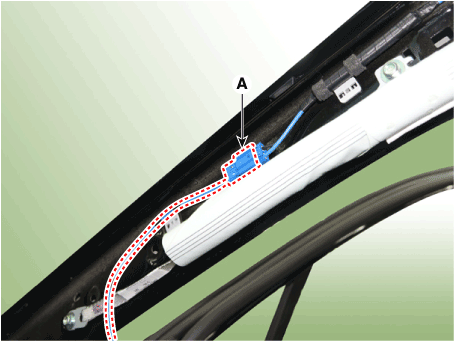
Loosen the mounting clips (B) in the front pillar and Disconnect the
connectors (A).
[Driver]
[Passenger]
|
| 25. |
Remove the drain hose (A).
|
| 26. |
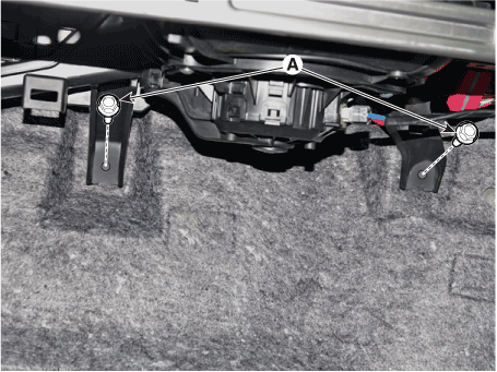
Remove the lower mounting bolt of the blower unit.
[Driver]
[Passenger]
|
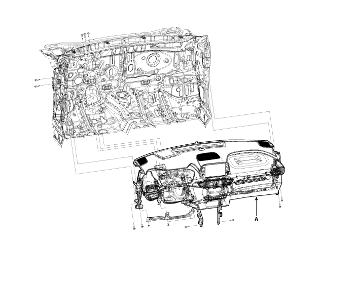
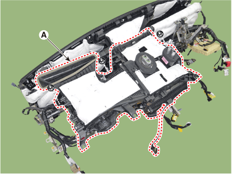
| 27. |
After loosening the bolts and nuts remove the crash pad and heater &
blower unit assembly (A) together.
|
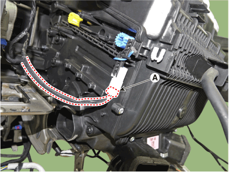
| 28. |
Disconnect the heater & blower unit connectors.
|
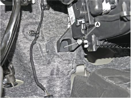
| 29. |
Loosen the heater & blower unit mounting bolt (A).
|
| 30. |
Loosen the mounting nuts and remove the heater & blower unit (A) from
the crash pad.
|
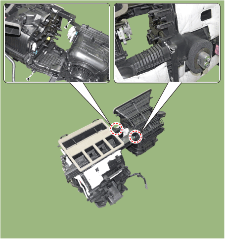
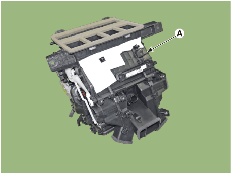
| 31. |
Loosen the mounting screw and separate the heater unit (A).
|
| 32. |
Install in the reverse order of removal.
|
Heater Core. Repair procedures
| Replacement |
| 1. |
Disconnect the negative (-) battery terminal.
|
| 2. |
Remove the heater and blower assembly.
(Refer to Heater - "Heater Unit")
|
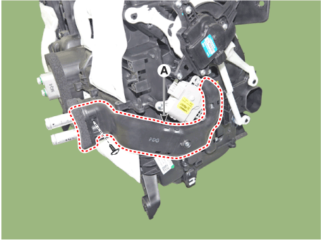
| 3. |
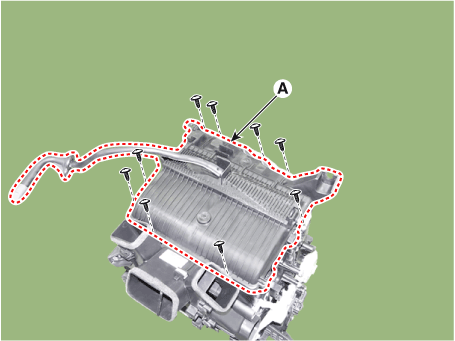
Loosen the mounting screws and remove the heater core cover (A).
|
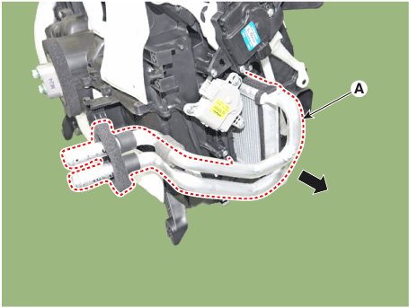
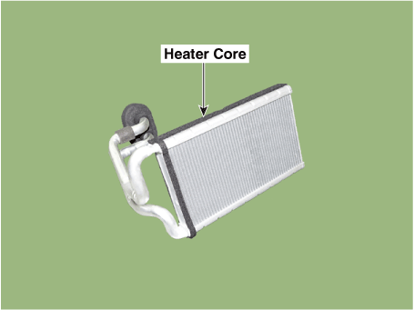
| 4. |
Separate the heater core (A) from the heater unit.
|
| 5. |
Install in the reverse order of removal.
|
Evaporator Core. Repair procedures
| Replacement |
| 1. |
Disconnect the negative (-) battery terminal.
|
| 2. |
Remove the heater and blower assembly.
(Refer to Heater - "Heater Unit")
|
| 3. |
Remove the heater core.
(Refer to Heater - "Heater Core")
|
| 4. |
Loosen the mounting screws and remove the evaporator core cover (A).
|
| 5. |
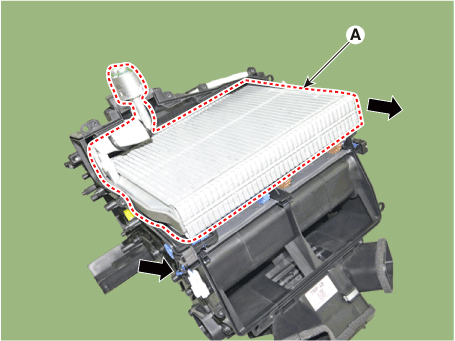
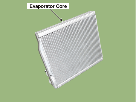
Remove the evaporator core (A) from the heater unit.
|
| 6. |
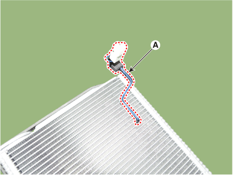
Remove the evaporator temperature sensor (A) from the evaporator core.
|
| 7. |
Install in the reverse order of removal.
|
PTC Heater (Diesel only). Description and operation
| Description |
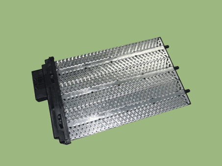
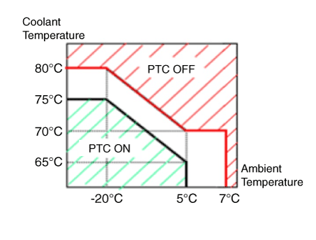
| • |
Battery voltage : 13V or above
|
| • |
Engine : Running
|
| • |
Ambient temperature and coolant temperature
|
PTC Heater (Diesel only). Repair procedures
| Inspection |
| 1. |
Entering
|
| 2. |
Forced operation
|
| 3. |
Cancellation
|
| 1. |
Run the engine.
|
| 2. |
Check the current on the wiring with a clamp multi tester.
|
| 3. |
If the current is not within specification, inspect the related wiring.
|
| 1. |
Turn the ignition switch OFF.
|
| 2. |
Disconnect the PTC heater connector.
|
| 3. |
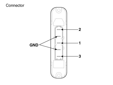
Measure the resistance between terminal 1, 2 of PTC heater and ground
line.
|
| 4. |
If the measured resistance is not within specification, replace the
PTC heater with a new one.
|
| Replacement |
| 1. |
Disconnect the negative (-) battery terminal.
|
| 2. |
Remove the cowl cross bar assembly.
(Refer to Body - "Cowl Cross Bar Assembly")
|
| 3. |
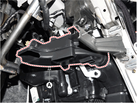
Loosen the mounting screw, remove the driver's shower duct (A).
|
| 4. |
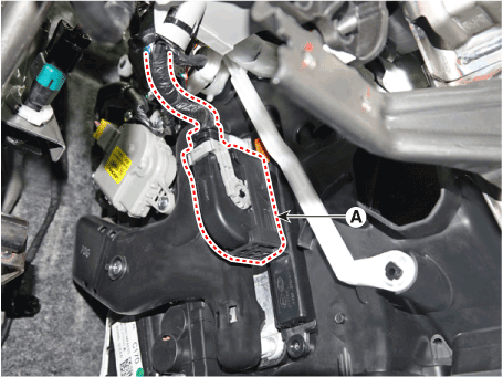
Press the lock pin, separate the PTC heater connector (A).
|
| 5. |
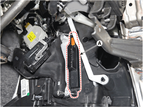
Loosen the mounting screws, remove the PTC heater (A).
|
| 6. |
Install in the reverse order of removal.
|
Temperature Control Actuator. Description and operation
| Description |
Temperature Control Actuator. Components and components location
| Component Location |
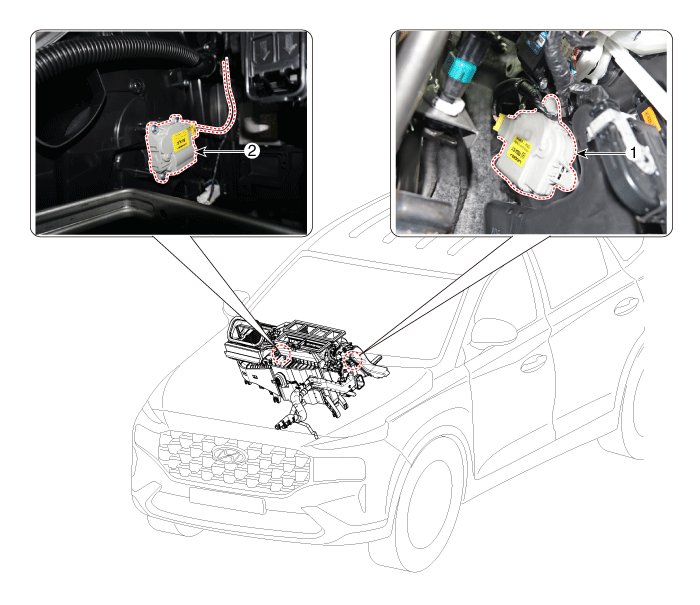
| 1. Driver side
Temperature control actuator |
2. Passenger
side Temperature control actuator |
Temperature Control Actuator. Repair procedures
| Inspection |
| 1. |
Turn the ignition switch OFF.
|
| 2. |
Disconnect the temperature control actuator connector.
|
| 3. |
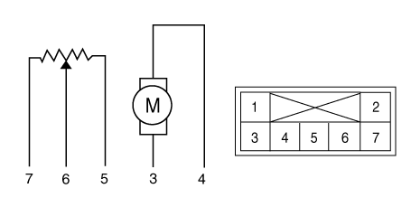
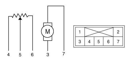
Verify that the temperature control actuator operates to the cool position
when connecting 12V to terminal 3 and grounding terminal 7.
Verify that the temperature control actuator operates to the warm position
when connected in reverse.
[Driver]
[Passenger]
|
| 4. |
Connect the temperature control actuator connector.
|
| 5. |
Turn the ignition switch ON.
|
| 6. |
Check the voltage between terminal 5 and 6.
Specification
It will feedback the current position of the actuator to controls.
|
| 7. |
If the measured voltage is not within specification, substitute with
a known-good temperature control actuator and check for proper operation.
|
| 8. |
Replace the temperature control actuator if it is proved that there
is a problem with it.
|
| Replacement |
| 1. |
Disconnect the negative (-) battery terminal.
|
| 2. |
Remove the crash pad lower panel.
(Refer to Body - "Crash Pad Lower Panel")
|
| 3. |
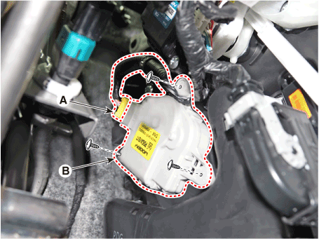
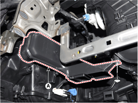
Loosen the mounting screw and remove the driver shower duct (A).
|
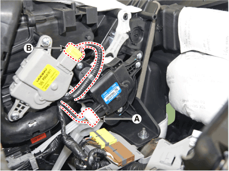
| 4. |
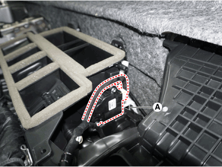
Separate the temperature control actuator connector (A) and loosen the
mounting screw and remove the temperature control actuator (B).
|
| 5. |
Install in the reverse order of removal.
|
| 1. |
Disconnect the negative (-) battery terminal.
|
| 2. |
Remove the crash pad center panel.
(Refer to Body - "Crash Pad Center Panel")
|
| 3. |
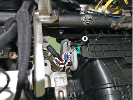
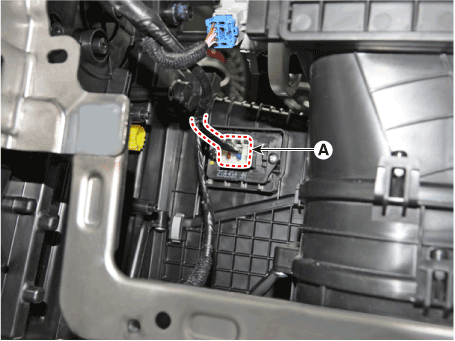
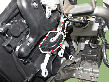
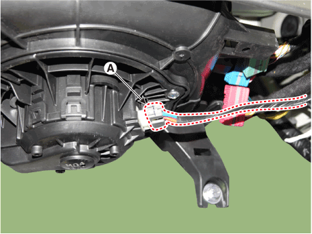
Loosen the mounting screw and remove the passenger shower duct (A).
|
| 4. |
Separate the temperature control actuator connector (A) and loosen the
mounting screw and remove the temperature control actuator (B).
|
| 5. |
Install in the reverse order of removal.
|
Mode Control Actuator. Description and operation
| Description |
Mode Control Actuator. Components and components location
| Components Location |
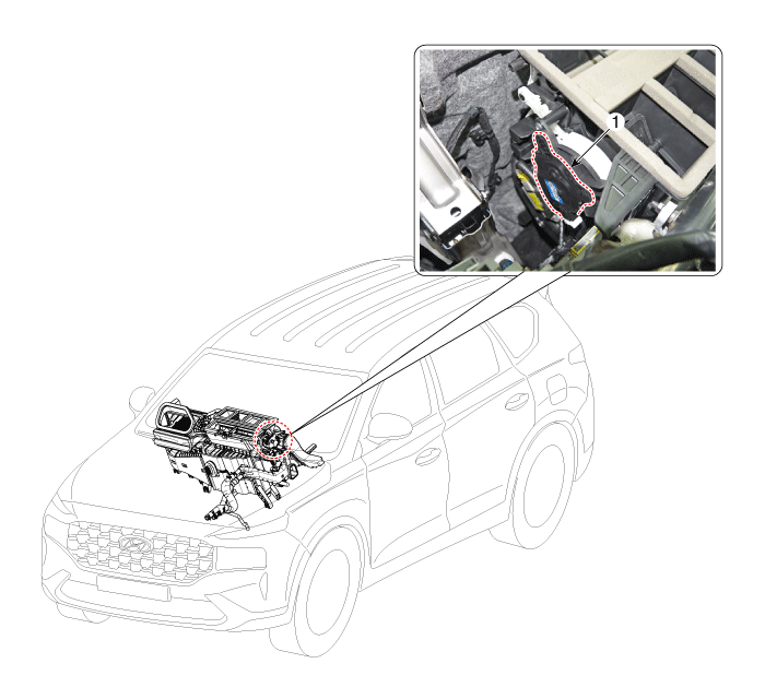
| 1. Mode Control
Actuator |
Mode Control Actuator. Repair procedures
| Inspection |
| 1. |
Turn the ignition switch OFF.
|
| 2. |
Disconnect the mode control actuator connector.
|
| 3. |
Verify that the mode control actuator operates to the defrost mode when
connecting 12V to terminal 3 and grounding terminal 7.
Verify that the mode control actuator operates to the vent mode when
connected in reverse.
|
| 4. |
Connect the mode control actuator connector.
|
| 5. |
Turn the ignition switch ON.
|
| 6. |
Check the voltage between terminal 5 and 4.
Specification
It will feedback the current position of the actuator to controls.
|
| 7. |
If the measured voltage is not within specification, substitute with
a known-good mode control actuator and check for proper operation.
|
| 8. |
Replace the mode control actuator if it is proved that there is a problem
with it.
|
| Replacement |
| 1. |
Disconnect the negative (-) battery terminal.
|
| 2. |
Remove the main crash pad assembly.
(Refer to Body - "Main Crash Pad Assembly")
|
| 3. |
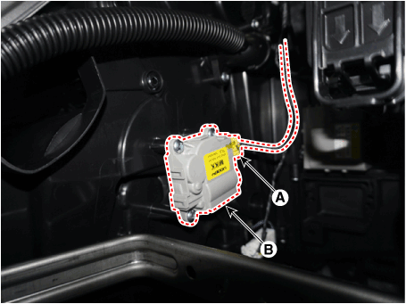
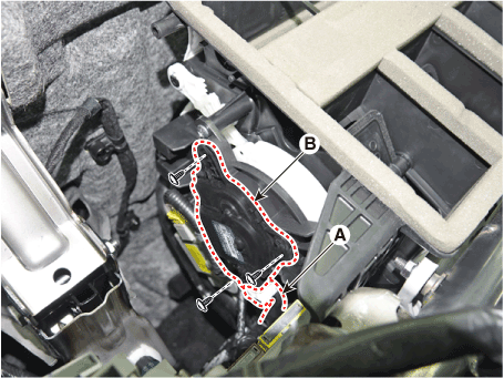
Separate the mode control actuator connector (B) and loosen the mounting
screw and remove the mode control actuator (A).
|
| 4. |
Install in the reverse order of removal.
|
Auto Defogging Actuator. Description and operation
| Description |
Auto Defogging Actuator. Components and components location
| Components Location |
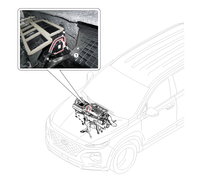
| 1. Auto defogging
actuator |
Auto Defogging Actuator. Repair procedures
| Inspection |
| 1. |
Turn the ignition switch OFF.
|
| 2. |
Disconnect the auto defogging connector.
|
| 3. |
Verify that the auto defogging actuator operates to the open position
when connecting 12V to terminal 3 and grounding terminal 6.
Verify that the auto defogging actuator operates to the close position
when connected in reverse.
|
| 4. |
Connect the auto defogging actuator connector.
|
| 5. |
Turn the ignition switch ON.
|
| 6. |
Check the voltage between terminals 5 and 4.
Specification
|
| 7. |
If the measured voltage is not within specification, check the operation
by replacing the existing auto defogging actuator with a new genuine
part. After that, determine whether replacement of the auto defogging
actuator is required or not.
|
| Replacement |
| 1. |
Disconnect the negative (-) battery terminal.
|
| 2. |
Remove the main crash pad assembly.
(Refer to Body - "Main Crash Pad Assembly")
|
| 3. |
Press the lock pin and separate the connector (A) and loosen the mounting
screws and remove the auto defogging actuator (B).
|
| 4. |
Install in the reverse order of removal.
|
 Air conditioning System
General safety information and caution Instructions (R-134a) When Handling Refrigerant 1. R-134a liquid refrigerant is highly volatile. A drop on the skin of your hand could result in localized frostbite. ...
 Blower
Blower Unit. Components and components location Components Location 1. Blower unit assembly Components 1. Blower unit assembly 2. Inlet case [LH] 3. Inlet seal 4. Inlet case [RH] 5. Intake actuator 6. ...
See also:
Components and Components Location
Components Location 1. Receiver 2. TPMS Sensor (FL) 3. TPMS Sensor (RL) 4. TPMS Sensor (RR) 5. TPMS Sensor (FR) ...
Air bag warning label
Air bag warning labels, some required by the U.S. National Highway Traffic Safety Administration (NHTSA), are attached to alert the driver and passengers of potential risks of the air bag system. ...
Power brakes
Your vehicle has power-assisted brakes that adjust automatically through normal usage. In the event that the power-assisted brakes lose power because of a stalled engine or some other reason, you can still ...

