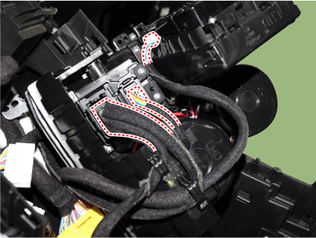
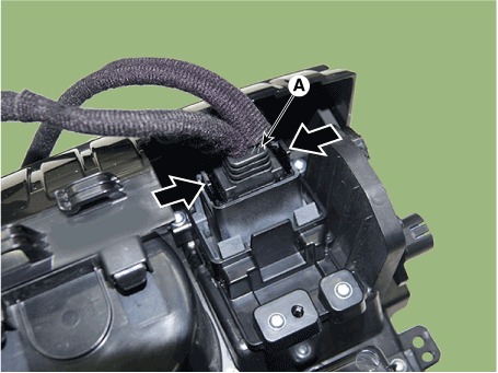
 Hyundai Santa Fe (TM): Audio
Components and components location
| Component Location |
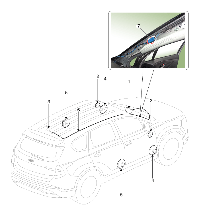
| 1. Audio unit 2. Tweeter speaker 3. Roof antenna (Radio) 4. Front door speaker |
5. Rear door
speaker 6. Antenna feeder cable 7. Antenna cable connector |
Specifications
| Specifications |
|
Item |
Specification |
||
|
Model |
RADIO (MONO Type) |
RADIO (TFT Type) |
|
|
Power supply |
DC 14.4V |
||
|
Parasitic current |
Max. 2mA (Head unit only) |
||
|
Antenna |
80PF 75Ω |
||
|
Tuning type |
PLL synthesized type |
||
|
Frequency range / Channel space |
FM |
87.5 - 108.0 MHz/100 KHz |
|
|
AM |
87.5 - 108.0 MHz/100 KHz |
||
Audio Unit. Components and components location
| Components |
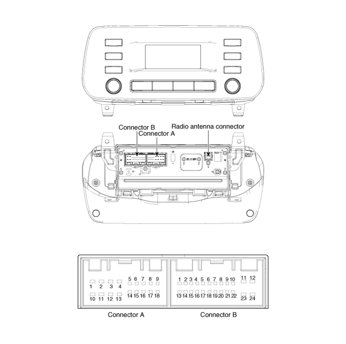
|
No |
Connector A |
Connector B |
|
1 |
Rear left speaker (+) |
- |
|
2 |
Front left speaker (+) |
- |
|
3 |
Front right speaker (+) |
- |
|
4 |
Rear right speaker (+) |
Steering wheel remote |
|
5 |
- |
- |
|
6 |
Door open |
USB DATA (+) |
|
7 |
IGN1 |
USB VOC |
|
8 |
Illumination (+) |
- |
|
9 |
Detent |
- |
|
10 |
Rear left speaker (-) |
Mic (+) |
|
11 |
Front left speaker (-) |
ACC |
|
12 |
Front right speaker (-) |
B+ |
|
13 |
Rear right speaker (-) |
- |
|
14 |
- |
- |
|
15 |
- |
- |
|
16 |
- |
Vehicle Speed |
|
17 |
Illumination (-) |
Steering wheel remote GND |
|
18 |
- |
USB DATA (-) |
|
19 |
|
USB GND |
|
20 |
- |
|
|
21 |
- |
|
|
22 |
Mic (-) |
|
|
23 |
- |
|
|
24 |
GND |

Audio Unit. Repair procedures
| Removal |
| 1. |
Disconnect the negative (-) battery terminal.
|
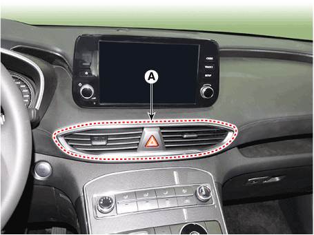
| 2. |
Remove the center air vent duct (A).
|
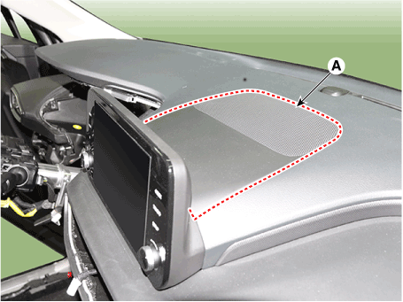
| 3. |
Remove the center speaker (A).
|
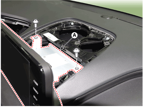
| 4. |
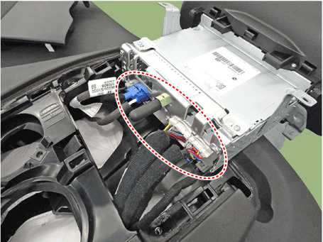
Seperate the audio head unit (A) from crash pad after loosening the
screws.
|
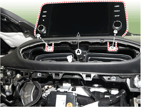
| 5. |
Remove the audio head unit after disconnecting the connectors and cable.
|
| Installation |
| 1. |
Connect the audio unit connectors and cable.
|
| 2. |
Install the audio head unit.
|
| 3. |
Install the center air vent duct.
|
| 4. |
Connect the negative (-) battery terminal.
|
Speakers. Repair procedures
| Inspection |
| 1. |
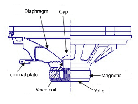
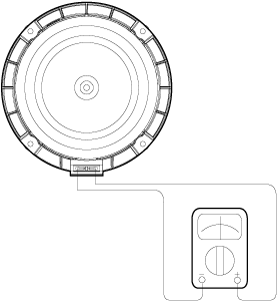
Troubleshooting for Speaker
|
| Removal |
| 1. |
Remove the front door trim.
(Refer to Body - "Front Door Trim")
|
| 2. |
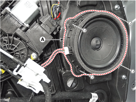
Disconnect the speaker connector.
|
| 3. |
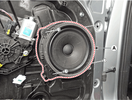
Remove the front speaker (A) after loosening the screws (4EA).
|
| 1. |
Remove the rear door trim.
(Refer to Body - "Rear Door Trim")
|
| 2. |
Disconnect the speaker connector.
|
| 3. |
Remove the rear speaker (A) after loosening the screws (4EA).
|
| 1. |
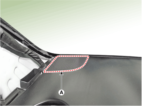
Using a screwdriver or remover, remove the tweeter speaker cover (A).
|
| 2. |
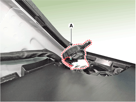
Remove the tweeter speaker (A) by loosening the screw and then disconnect
the speaker connector.
|
| Installation |
| 1. |
Install the front speaker.
|
| 2. |
Install the front door trim.
|
| 1. |
Install the rear speaker.
|
| 2. |
Install the rear door trim.
|
| 1. |
Connect the connector.
|
| 2. |
Install the tweeter speaker and speaker cover.
|
Antenna. Components and components location
| Components |
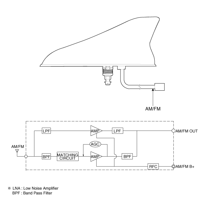
Antenna. Repair procedures
| Removal |
| 1. |
Remove the rear roof trim.
(Refer to Body - "Roof Trim Assembly")
|
| 2. |
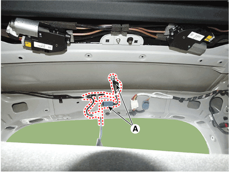
Disconnect the roof antenna connectors (A) from the roof antenna.
|
| 3. |
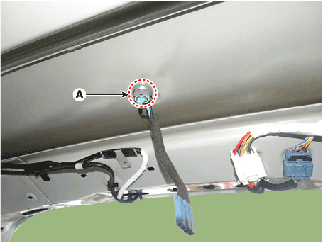
Remove the roof antenna after removing a nut (A).
|
| Installation |
| 1. |
Connect the roof antenna connectors.
|
| 2. |
Install the rear roof trim.
|
Audio Remote Control. Components and components location
| Components |
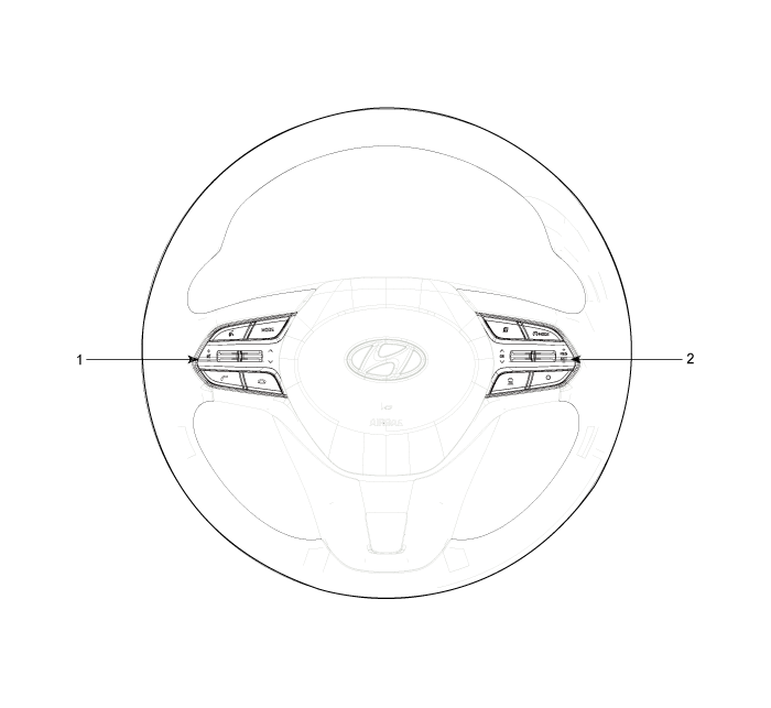
| 1. Remote control
switch (LH : Audio) |
2. Remote control
switch (RH : Cruise+Flex) |
Audio Remote Control. Schematic diagrams
| Circuit Diagram |
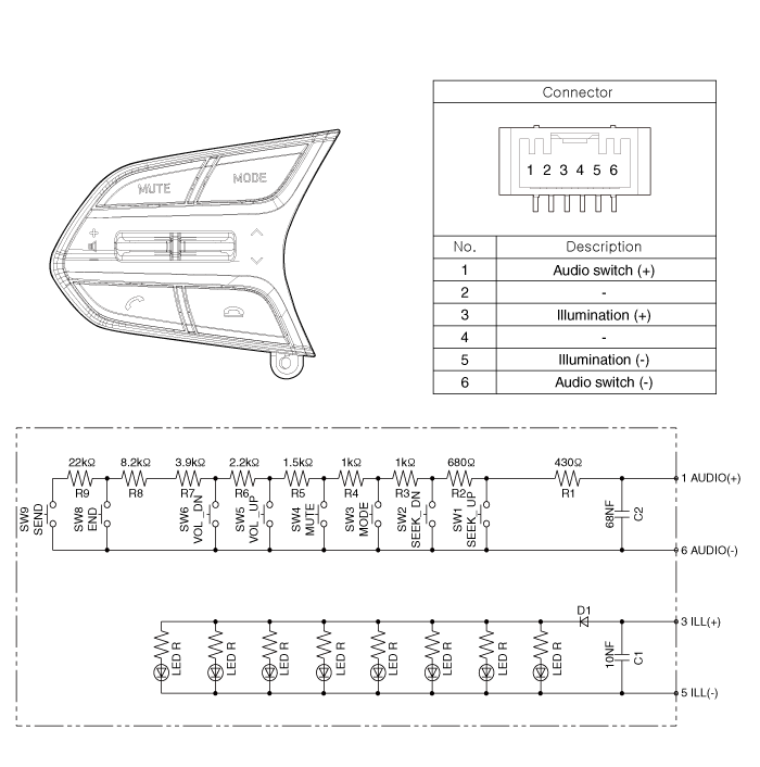
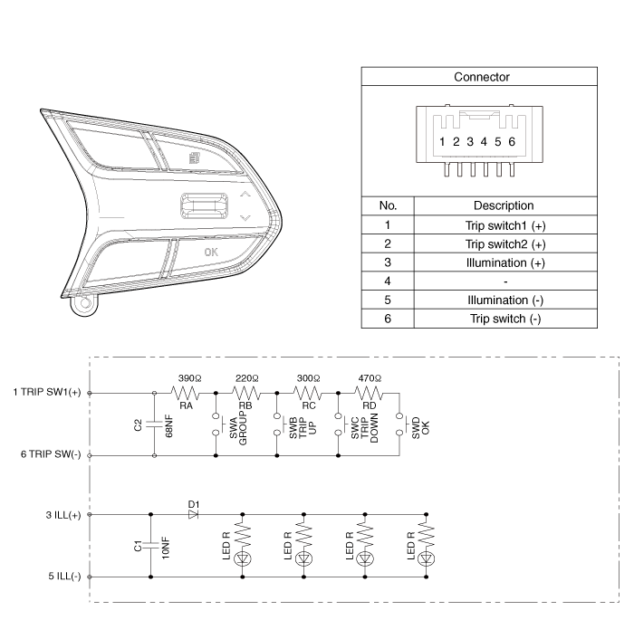
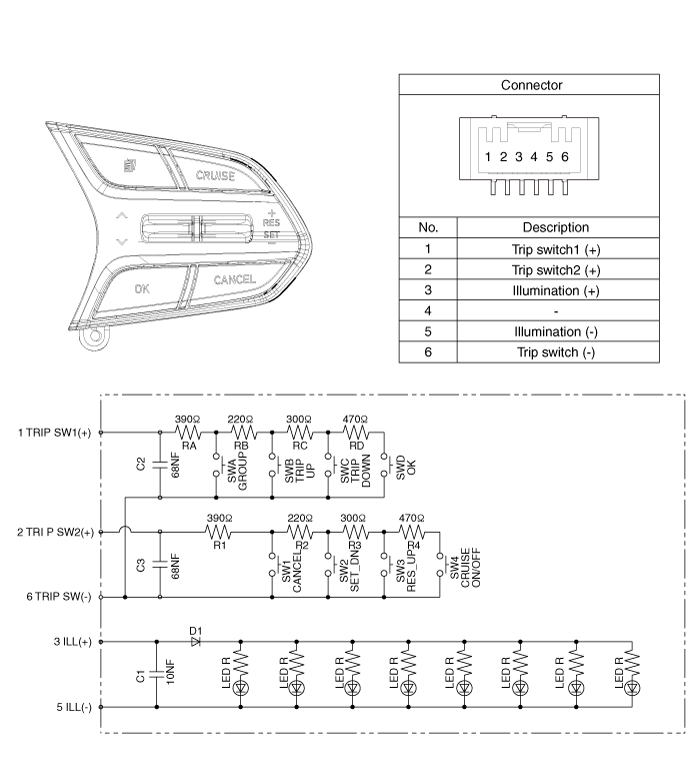
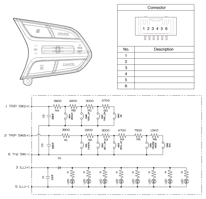
Audio Remote Control. Repair procedures
| Inspection |
| 1. |
Check for resistance between terminals in left switch position.
[Audio/Bluetooth]
|
| 2. |
Check for resistance between terminals in right switch position.
[Trip/Cruise]
|
| Removal |
| 1. |
Disconnect the negative (-) battery terminal.
|
| 2. |
Remove the driver airbag module.
(Refer to Restraint - "Driver Airbag (DAB) Module and Clock Spring")
|
| 3. |
Remove the steering wheel.
(Refer to Steering System - "Steering Column and Shaft")
|
| 4. |
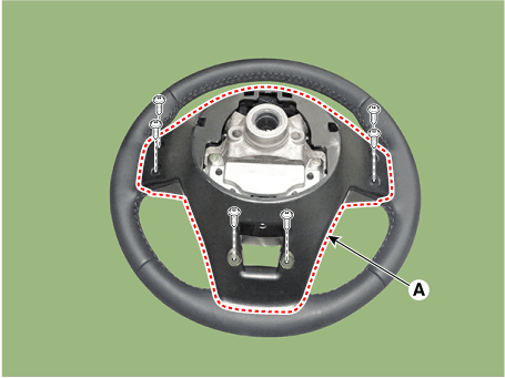
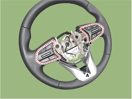
Remove the steering wheel cover (A) after loosening the screws.
|
| 5. |
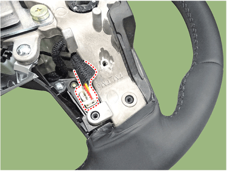
Loosen the screws and then disconnect the steering wheel remote control
switch connector.
|
| 6. |
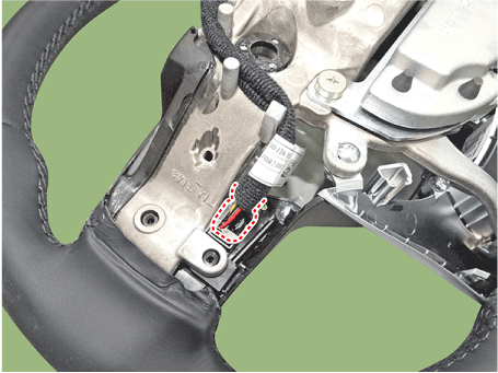
Remove the remote control switchs (A).
|
| Installation |
| 1. |
Install the remote control switch on the steering wheel.
|
| 2. |
Install the steering wheel.
|
| 3. |
Reconnect the remote control switch connector and airbag connectors.
|
| 4. |
Install the driver airbag module.
|
| 5. |
Connect the negative (-) battery terminal.
|
USB Jack. Description and operation
| Description |
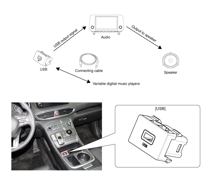
USB Jack. Schematic diagrams
| Circuit Diagram |
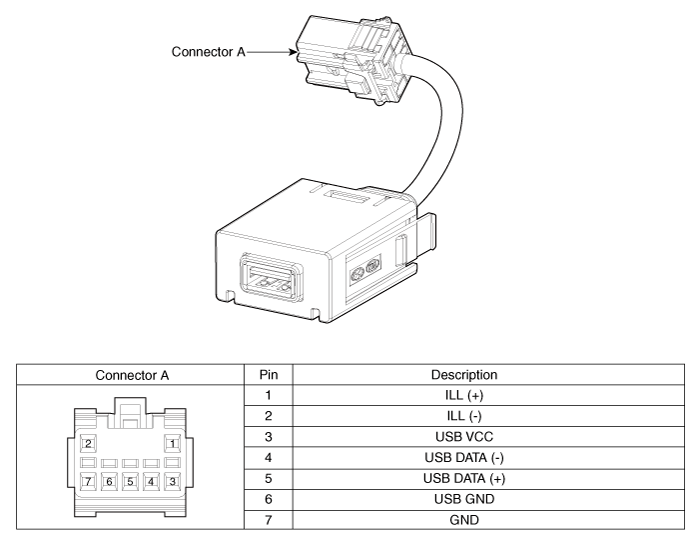
USB Jack. Repair procedures
| Removal |
|
|
| 1. |
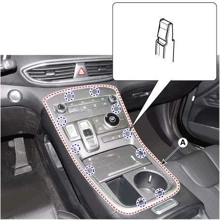
Remove the console upper cover (A).
|
| 2. |
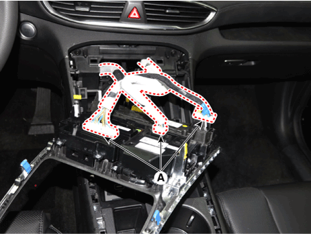
Press the lock pin, separate the connectors (A).
|
| 3. |
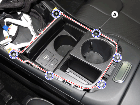
Remove the cup holder assembly (A) after loosening mounting screws.
|
| 4. |
Disconnect WPC, USB, WPC lamp connectors.
|
| 5. |
Remove the USB (A) by pushing the fixed clip in the direction of the
arrow as lillustration below.
|
| Installation |
| 1. |
Install the USB.
|
| 2. |
Install the cup holder assembly.
|
| 3. |
Install the floor console upper cover.
|
| 4. |
Connect the negative (-) battery connector.
|
 Special service tools
Special Service Tools Tool (Number and Name) Illustration Application Correction jig for LDW or LKA (09890-3V100) Correction of LDW (Lane Departure Warning) or LKA (Lane Keeping Assist). Vertical Measuring ...
 Multifunction Switch
Components and components location Component 1. Steering column 2. Multifunction switch 3. Screw 4. Clock spring Specifications Specifications Items Specifications Rated voltage DC 12V Operating temperature ...
See also:
Components and Components Location
Component Location 1. Driver power window main switch 2. Passenger window switch 3. IPM (Intalligent intergrated Platform Module) 4. Door lock switch 5. Tailgate lock actuator & switch 6. Front door ...
Pressure Sensor. Repair procedures
Inspection If you have trouble code related to the pressure sensor check pressure sensor according to the inspection process. Pressure Sensor Inspection Procedure Measure the resistance of pressure sensor ...
High Mounted Stop Lamp. Repair procedures
Removal High Mounted Stop Lamp 1. Disconnect the negative (-) battery terminal. 2. Remove the rear spoiler. 3. Remove the high mounted stop lamp assembly (A) after loosening screws (4EA). Installation ...

