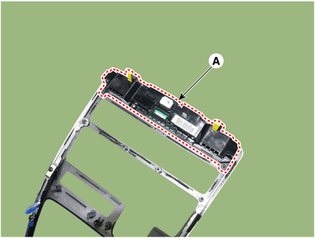
 Hyundai Santa Fe (TM): AVN System
Description and operation
| Description |
AVN system
The AVN system has improved information search and easiness of manipulation
for the driver by simplifying the system operation experience and unifying the
display of the user information such as multimedia and car information.
The system is basically composed of a keyboard for the operation of combined
function, LCD monitor, a head unit with Bluetooth handsfree calling, voice recognition
and navigation, music amplifier and the media unit that connects with other
outside devices.
| 1. |
Simplification of user interface : the multimedia and car information
are displayed on the monitor.
|
| 2. |
Networked electronic parts : Efficient information transmission through
CAN communications.
|
| 3. |
Up-to-date technologies integrated :
|
System Block Diagram
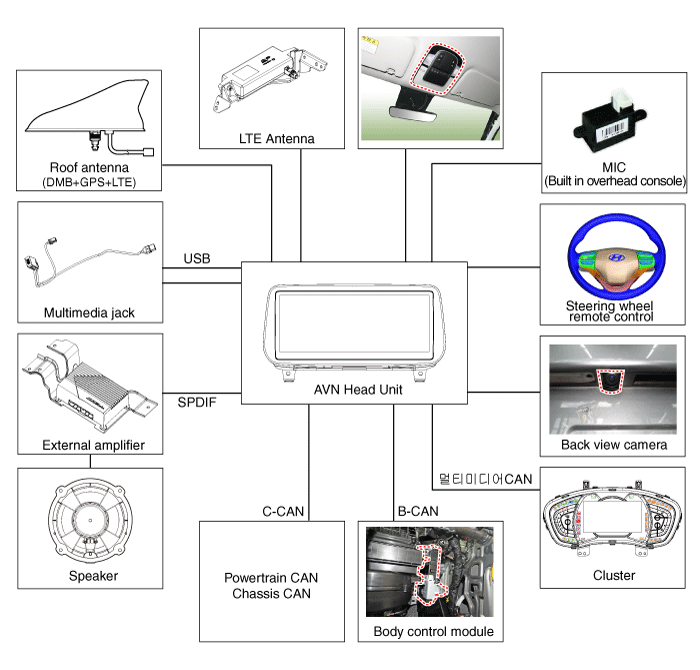
| • |
B-CAN : Body Controller Area Network
|
| • |
MM-CAN : Multi-Media Controller Area Network
|
Limitations Of The Navigation system
GPS Signal Reception State
As the GPS satellite frequency is received/transmitted in straight lines, reception
may not work if hiding devices are placed on or near the GPS antenna or when
traveling through the following locations.
| • |
Tunnels
|
| • |
Basement parking structures
|
| • |
Underneath an overpass
|
| • |
Roads within forested areas
|
| • |
Areas near high rise buildings
|
| • |
Roads within canyons
|
Vehicle Position Display
| 1. |
If multipass errors occur due to reflections from buildings or related
causes, the current position mark on the navigation may differ from
the actual position of the vehicle.
|
| 2. |
The position of the vehicle on the navigation may be different from
the actual position if the vehicle is under the occur, driving for a
short period of time will vehicle through map matching or GPS information
(several minutes may be necessary in certain cases).
|
Route Guidance
Suitable route guidance may not occur caused by search conditions or the driving
position.
| • |
Guidance to go straight may be given while driving on a straight road.
|
| • |
Guidance may not be given even when having turned at an intersection.
|
| • |
There are certain intersections in which guidance may not occur.
|
| • |
A route guidance signaling entrance into a no enter zone may occur (No
enter zone, road under construction, etc.)
|
| • |
Guidance may be given to a position removed from the actual destination
if roads to reach the actual destination do not exist or are too narrow.
|
| • |
Faulty voice guidance may be given if the vehicle breaks from the designated
route (ex : if a turn is made at an intersection while the navigation
provided guidance to go straight).
|
| • |
Map Data may be missing or incorrect causing route guidance to not be
given.
|
Route Re-calculation
The following phenomena may occur after conducting route recalculation.
| • |
When turning at an intersection, the navigation system gives wrong information
on the current position.
|
| • |
Route recalculation may take a longer period of time when driving under
high speeds.
|
| • |
A route guidance signaling for a U-Turn in a No U-Turn location may
occur.
|
| • |
A route guidance signaling entrance into a no enter zone may occur (No
enter zone, road under construction, etc).
|
| • |
Guidance may be given to a position removed from the actual destination
do not exist or are too narrow.
|
| • |
Faulty voice guidance may be given if the vehicle breaks from the designated
route (ex : if a turn is made at an intersection while the navigation
provided guidance to go straight)
|
Components and components location
| Components Location |
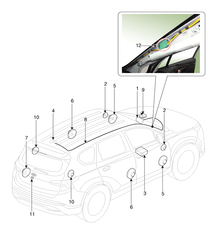
| 1. AVN (A/V &
Navigation head unit) 2. Tweeter speaker 3. External amplifier 4. Roof antenna 5. Front door speaker 6. Rear door speaker |
7. Subwoofer
speaker 8. Antenna feeder cable 9. Center speaker 10. Surround speaker 11. Back view camera 12. Feeder cable joint connector |
Specifications
| Specifications |
|
Item |
Specification |
|
Power source |
DC 14.4V (-) ground |
|
Frequency range / Channel space |
FM : 87.5 - 108.0 MHz / 100 KHz AM : 531 - 1602 KHz / 9 KHz |
|
Tuning type |
PLL SYNTHESIZED TUNING |
|
Impedance |
2 ohm x 4 |
|
Antenna |
80 pF 75 ohm |
|
parastic current |
MAX 2mA (Head unit only) |
|
S/N |
FM : MIN 50 dB AM : MIN 40 dB |
AVN Head Unit. Components and components location
| Components |
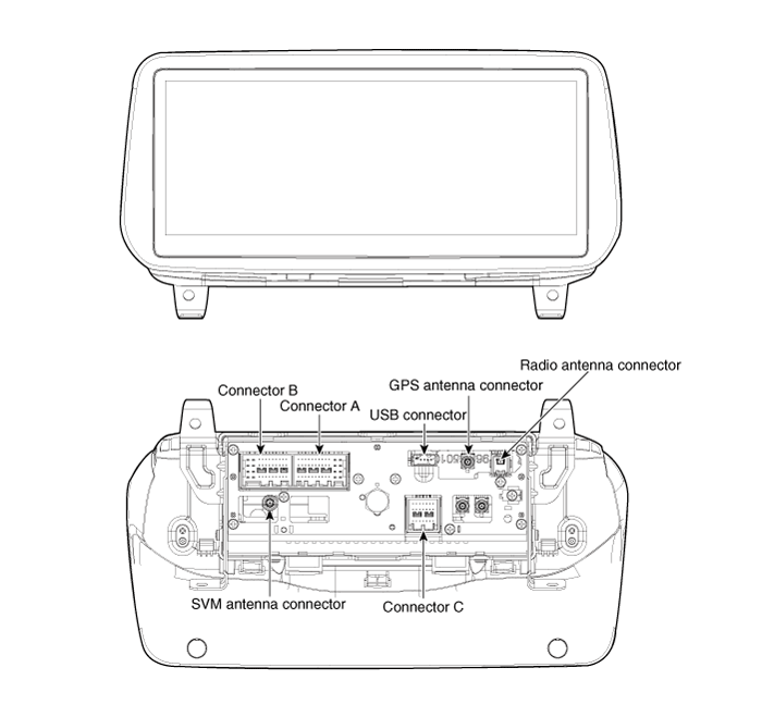
Connector Pin Information
|
No |
Connector A (ExternalAmplifier) |
Connector A (Internal Amplifier) |
Connector B |
Connector C |
|
1 |
- |
Rear door speaker LH (+) |
- |
- |
|
2 |
- |
Rear door speaker LH (-) |
Mic (+) |
I -CAN (High) |
|
3 |
Navigation voice (+) |
- |
- |
- |
|
4 |
External amplifier SPDIF (+) |
- |
- |
- |
|
5 |
Reset |
Reset |
- |
- |
|
6 |
Camera power (RVM) |
Camera power (RVM) |
Illumination (+) |
- |
|
7 |
Camera video (RVM) |
Camera video (RVM) |
M-CAN (High) |
- |
|
8 |
- |
- |
- |
- |
|
9 |
- |
- |
- |
I -CAN (Low) |
|
10 |
- |
- |
Battery (+) |
- |
|
11 |
DETECT |
DETECT |
Battery (+) |
- |
|
12 |
Steering wheel remote |
Steering wheel remote |
Ground |
- |
|
13 |
- |
Front door speaker LH (+) |
- |
- |
|
14 |
- |
Front door speaker LH (-) |
- |
- |
|
15 |
- |
Front door speaker RH (-) |
Mic (-) |
- |
|
16 |
- |
Front door speaker RH (+) |
- |
MTS |
|
17 |
Navigation voice (-) |
- |
- |
- |
|
18 |
External amplifier SPDIF (-) |
- |
- |
- |
|
19 |
External amplifier SPDIF (Ground) |
- |
Illumination (-) |
- |
|
20 |
Camera power_Ground (RVM) |
Camera power_Ground (RVM) |
M-CAN (Low) |
- |
|
21 |
Camera video ground (RVM) |
Camera video ground (RVM) |
- |
- |
|
22 |
- (SVM type:SVM video ground) |
- (SVM type:SVM video ground) |
ACC |
|
|
23 |
- |
- |
Keyboard power |
|
|
24 |
- |
- |
- |
|
|
25 |
- |
- |
- |
|
|
26 |
Steering wheel remote ground |
Steering wheel remote ground |
- |
|
|
27 |
- |
Rear door speaker RH (-) |
- |
|
|
28 |
- |
Rear door speaker RH (+) |
- |
|
|
29 |
- |
- |
- |
|
|
30 |
- |
- |
- |
|
|
31 |
- |
- |
- |
|
|
32 |
- (SVM type:SVM Detect1) |
- (SVM type:SVM Detect1) |
- |
|
|
33 |
Camera video shield (RVM) |
Camera video shield (RVM) |
IGN 1 |
|
|
34 |
- (SVM type:SVM video shield ) |
- (SVM type:SVM video shield ) |
Keyboard ground |
|
|
35 |
- |
- |
Ground |
|
|
36 |
- |
- |
|
|
|
37 |
- |
- |
||
|
38 |
Vehicle speed |
Vehicle speed |
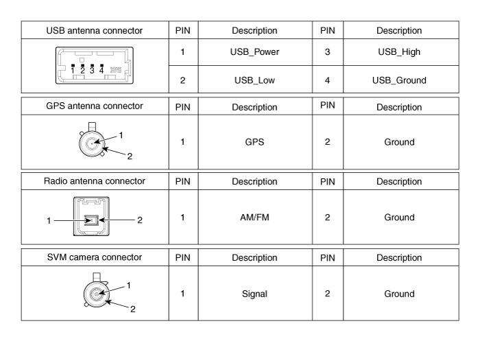
AVN Head Unit. Repair procedures
| Removal |
| 1. |
Disconnect the negative (-) battery terminal.
|
| 2. |
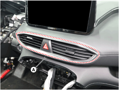
Remove the center air vent duct (A).
|
| 3. |
Remove the center speaker (A).
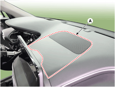
|
| 4. |
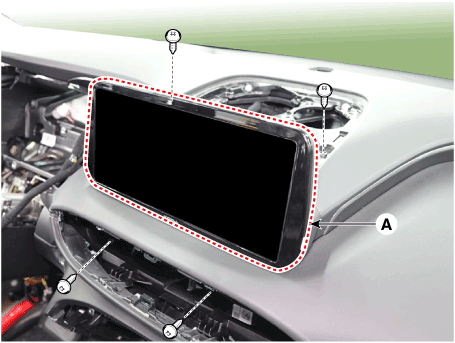
Remove the AVN head (A) unit after loosening mounting screws.
|
| 5. |
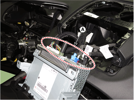
Remove the AVN head unit after disconnecting the connectors and cable.
|
| Installation |
| 1. |
Connect the audio unit connectors and cable.
|
| 2. |
Install the AVN head unit.
|
| 3. |
Install the center air vent duct.
|
| 4. |
Connect the negative (-) battery terminal.
|
AVN Remote Control. Components and components location
| Components |
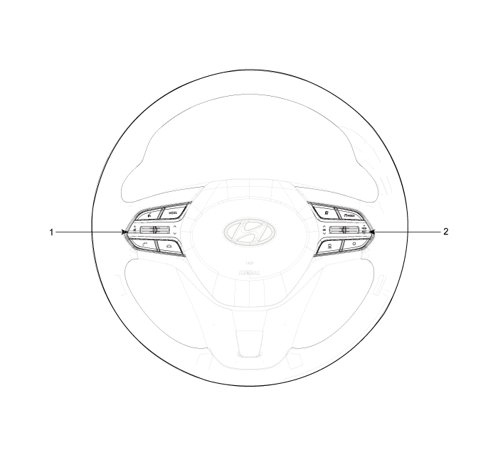
| 1. Remote control
switch (LH : Audio) |
2. Remote control
switch (RH : Cruise+Flex) |
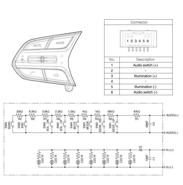
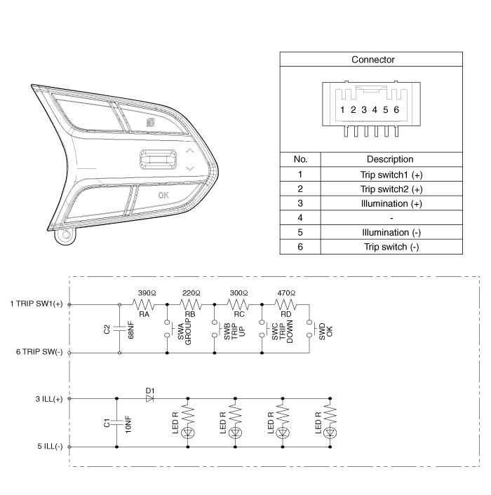
AVN Remote Control. Schematic diagrams
| Circuit Diagram |
[Audio/Bluetooth]
[Trip]
[Trip/Cruise]
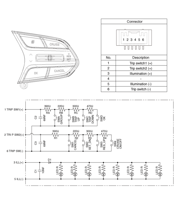
[Trip/Cruise/Smart Cruise]
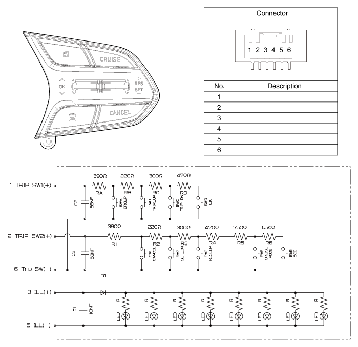
AVN Remote Control. Repair procedures
| Inspection |
| 1. |
Check for resistance between terminals in left switch position.
[Audio/Bluetooth]
|
| 2. |
Check for resistance between terminals in right switch position.
[Trip/Cruise]
|
| Removal |
| 1. |
Disconnect the negative (-) battery terminal.
|
| 2. |
Remove the driver airbag module.
(Refer to Restraint - "Driver Airbag (DAB) Module and Clock Spring")
|
| 3. |
Remove the steering wheel.
(Refer to Steering System - "Steering Column and Shaft")
|
| 4. |
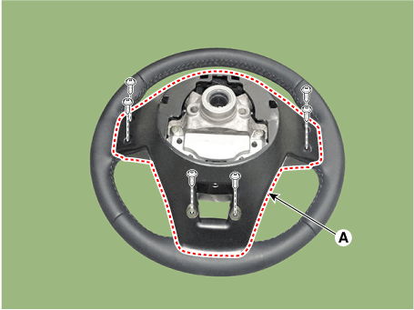
Remove the steering wheel cover (A) after loosening the screws.
|
| 5. |
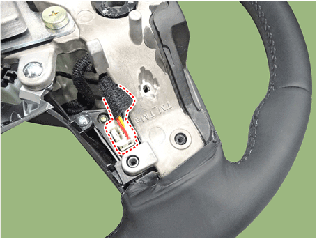
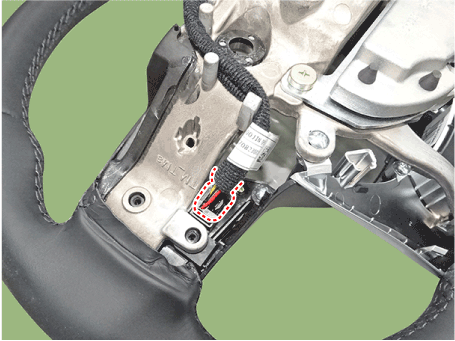
Loosen the screws and then disconnect the steering wheel remote control
switch connector.
|
| 6. |
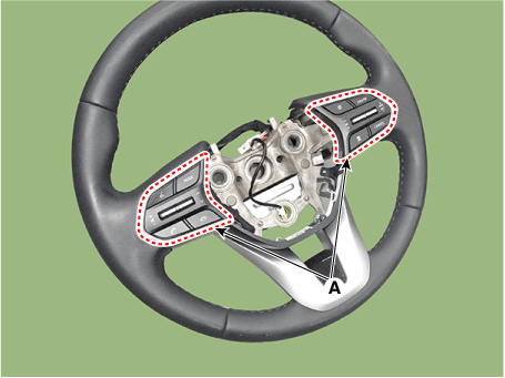
Remove the remote control switchs (A).
|
| Installation |
| 1. |
Install the remote control switch on the steering wheel.
|
| 2. |
Install the steering wheel.
|
| 3. |
Reconnect the remote control switch connector and airbag connectors.
|
| 4. |
Install the driver airbag module.
|
| 5. |
Connect the negative (-) battery terminal.
|
USB Jack. Description and operation
| Description |
The multimedia jack on the console upper cover is for customers who like to
listen to external portable music players like the MP3, through the vehicle's
sound system when it is linked to this jack. The customer has this added option.
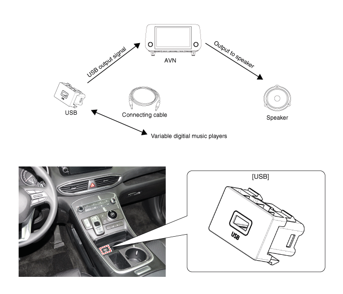
USB Jack. Schematic diagrams
| Circuit Diagram |
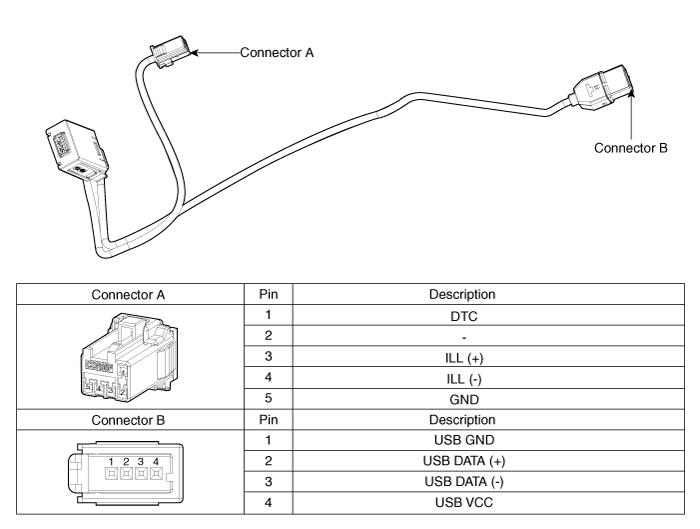
USB Jack. Repair procedures
| Removal |
|
|
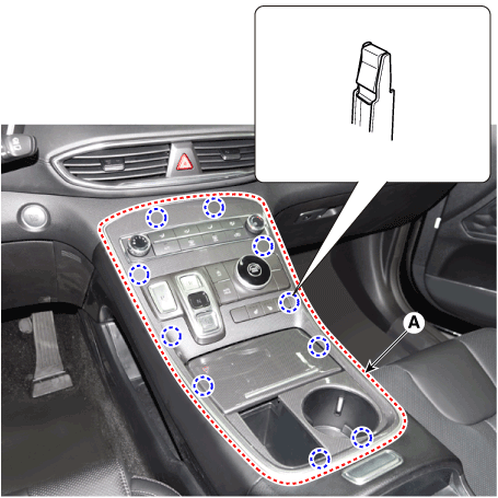
| 1. |
Remove the console upper cover (A).
|
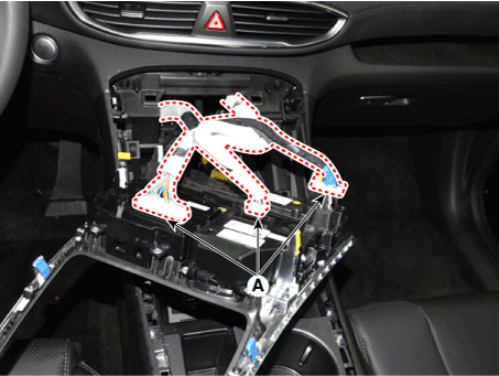
| 2. |
Press the lock pin, separate the connectors (A).
|
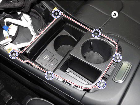
| 3. |
Remove the cup holder assembly (A) after loosening mounting screws.
|
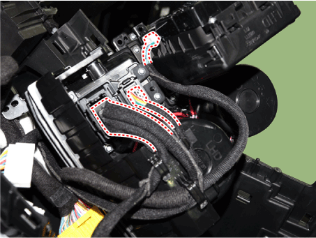
| 4. |
Disconnect WPC, USB, WPC lamp connectors.
|
| 5. |
Remove the USB (A) by pushing the fixed clip in the direction of the
arrow as lillustration below.
|
| Installation |
| 1. |
Install the USB.
|
| 2. |
Install the cup holder assembly.
|
| 3. |
Install the floor console upper cover.
|
| 4. |
Connect the negative (-) battery connector.
|
Speakers. Repair procedures
| Inspection |
| 1. |
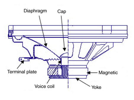
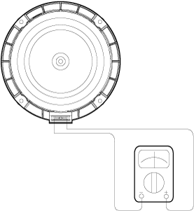
Troubleshooting for Speaker
|
| Removal |
Front Door Speaker
| 1. |
Disconnect the negative (-) battery terminal.
|
| 2. |
Remove the front door trim.
(Refer to Body - "Front Door Trim")
|
| 3. |
Disconnect the front door speaker connector.
|
| 4. |
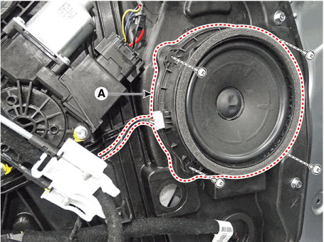
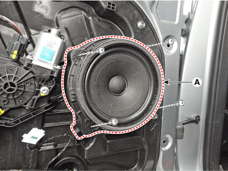
Remove the front door speaker (A) after loosening the screws.
|
Rear Door Speaker
| 1. |
Disconnect the negative (-) battery terminal.
|
| 2. |
Remove the rear door trim.
(Refer to Body - "Rear Door Trim")
|
| 3. |
Disconnect the rear door speaker connector.
|
| 4. |
Remove the rear door speaker (A) after loosening the screws.
|
Front Center Speaker
| 1. |
Disconnect the negative (-) battery terminal.
|
| 2. |
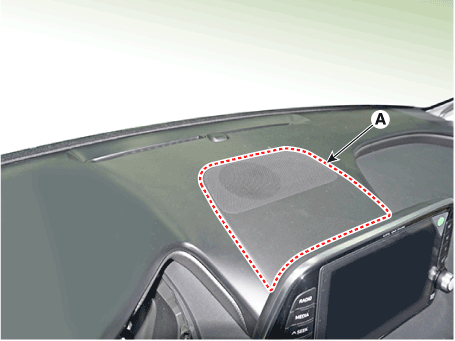
Remove the front center speaker grill (A).
|
| 3. |
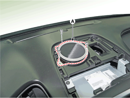
Remove the front center speaker (A) after loosening the screws.
|
| 4. |
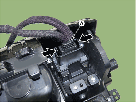
Disconnect the connector (A) and remove the front center speaker (B).
|
Tweeter Speaker (Front)
| 1. |
Disconnect the negative (-) battery terminal.
|
| 2. |
Remove the front pillar trim.
(Refer to Body - "Front Pillar Trim")
|
| 3. |
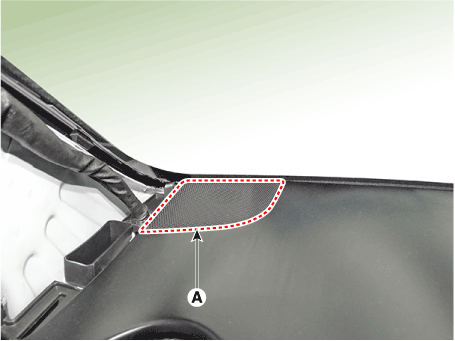
Remove the tweeter speaker cover (A).
|
| 4. |
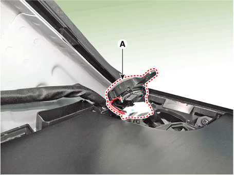
Remove the tweeter speaker (A) by loosening the screw and then disconnect
the speaker connector.
|
Woofer Speaker
| 1. |
Disconnect the negative (-) battery terminal.
|
| 2. |
Remove the luggage side trim [LH].
(Refer to Body - "Luggage Side Trim")
|
| 3. |
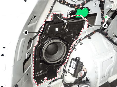
Disconnect the woofer speaker connector (A).
|
| 4. |
Remove the woofer speaker (B) after loosening the bolts and nuts.
|
Surround Speaker
| 1. |
Disconnect the negative (-) battery terminal.
|
| 2. |
Remove the luggage side trim.
(Refer to Body - "Luggage Side Trim")
|
| 3. |
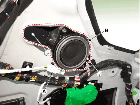
Disconnect the surround speaker connector (A).
|
| 4. |
Remove the surround speaker (B) after loosening the nuts.
|
| Installation |
Front Door Speaker
| 1. |
Install the front door speaker.
|
| 2. |
Connect the front door speaker connector.
|
| 3. |
Install the front door trim.
|
| 4. |
Connect the negative (-) battery terminal.
|
Rear Door Speaker
| 1. |
Install the rear door speaker.
|
| 2. |
Connect the rear door speaker connector.
|
| 3. |
Install the rear door trim.
|
| 4. |
Connect the negative (-) battery terminal.
|
Front Center Speaker
| 1. |
Connect the front center speaker connector.
|
| 2. |
Install the front center speaker.
|
| 3. |
Install the front center speaker grill.
|
| 4. |
Connect the negative (-) battery terminal.
|
Tweeter Speaker (Front)
| 1. |
Connect the speaker connector.
|
| 2. |
Install the tweeter speaker.
|
| 3. |
Install the tweeter speaker cover.
|
| 4. |
Install the front pillar trim.
|
| 5. |
Connect the negative (-) battery terminal.
|
Woofer Speaker
| 1. |
Install the woofer speaker.
|
| 2. |
Connect the woofer speaker connector.
|
| 3. |
Install the luggage side trim.
|
| 4. |
Connect the negative (-) battery terminal.
|
Surround Speaker
| 1. |
Install the surround speaker.
|
| 2. |
Connect the surround speaker connector.
|
| 3. |
Install the luggage side trim.
|
| 4. |
Connect the negative (-) battery terminal.
|
External Amplifier. Components and components location
| Components |
Europe
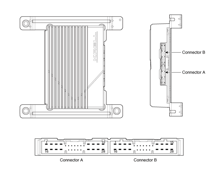
Connector Pin Information
|
No |
Connector A |
Connector B |
|
1 |
Battery (+) |
Rear left door speaker (+) |
|
2 |
Battery (+) |
Rear left door speaker (-) |
|
3 |
Battery (+) |
Rear right door speaker (+) |
|
4 |
Battery (+) |
Rear right door speaker (-) |
|
5 |
- |
- |
|
6 |
M-CAN (High) |
- |
|
7 |
M-CAN (Low) |
- |
|
8 |
ACC |
- |
|
9 |
Navigation voice (+) |
- |
|
10 |
- |
- |
|
11 |
- |
- |
|
12 |
Front left door speaker (+) |
Surround left speaker (+) |
|
13 |
Front left door speaker (-) |
Surround left speaker (-) |
|
14 |
Front right door speaker (+) |
Surround right speaker (+) |
|
15 |
Front right door speaker (-) |
Surround right speaker (-) |
|
16 |
Ground |
Sub woofer speaker1 (+) |
|
17 |
Ground |
Sub woofer speaker1 (-) |
|
18 |
Ground |
Sub woofer speaker2 (+) |
|
19 |
Ground |
Sub woofer speaker2 (-) |
|
20 |
SPDIF (+) |
- |
|
21 |
SPDIF (-) |
- |
|
22 |
SPDIF ground |
- |
|
23 |
Navigation voice (-) |
- |
|
24 |
IGN 1 |
|
|
25 |
Front left tweeter speaker (+) |
- |
|
26 |
Front left tweeter speaker (-) |
- |
|
27 |
Front right tweeter speaker (+) |
Center speaker (+) |
|
28 |
Front right tweeter speaker (-) |
Center speake (-) |
General
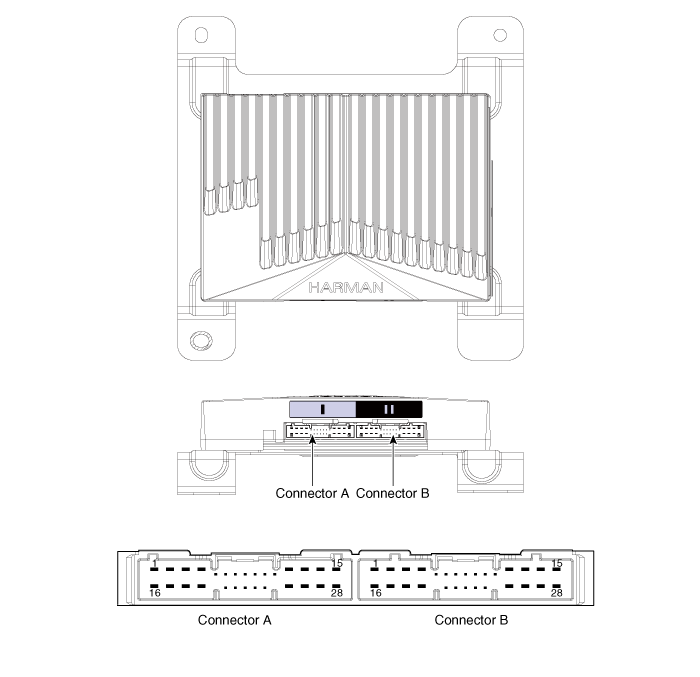
Connector Pin Information
|
No |
Connector A |
Connector B |
|
1 |
Battery (+) |
Sub woofer speaker2 (+) |
|
2 |
Battery (+) |
Sub woofer speaker1 (+) |
|
3 |
Battery (+) |
Front right door speaker (+) |
|
4 |
Battery (+) |
Front left door speaker (-) |
|
5 |
- |
- |
|
6 |
M-CAN (High) |
- |
|
7 |
M-CAN (Low) |
- |
|
8 |
ACC |
- |
|
9 |
Navigation voice (+) |
- |
|
10 |
- |
- |
|
11 |
- |
- |
|
12 |
Front right tweeter speaker (+) |
Rear right door speaker (+) |
|
13 |
Front left tweeter speaker (+) |
Rear left door speaker (+) |
|
14 |
Front center speaker (+) |
Surround right speaker (+) |
|
15 |
- |
Surround left speaker (+) |
|
16 |
Ground |
Sub woofer speaker2 (-) |
|
17 |
Ground |
Sub woofer speaker1 (-) |
|
18 |
Ground |
Front right door speaker (-) |
|
19 |
Ground |
Front left door speaker (-) |
|
20 |
SPDIF (High) |
- |
|
21 |
SPDIF (Low) |
- |
|
22 |
SPDIF ground |
- |
|
23 |
Navigation voice (-) |
- |
|
24 |
- |
- |
|
25 |
Front right tweeter speaker (-) |
Rear right door speaker (-) |
|
26 |
Front left tweeter speaker (-) |
Rear left door speaker (-) |
|
27 |
Front center speaker (-) |
Surround right speaker (-) |
|
28 |
- |
Surround left speaker (-) |
External Amplifier. Repair procedures
| Removal |
External Amplifier
| 1. |
Disconnect the negative (-) battery terminal.
|
| 2. |
Remove the passenger seat assembly.
(Refer to Body - "Front Seat Assembly")
|
| 3. |
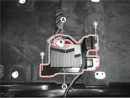
Remove the external amplifier (A) after disconnecting the connectors
and loosening the mounting bolts (3EA).
|
| Installation |
External Amplifier
| 1. |
Install the external amplifier after connecting the connector.
|
| 2. |
Install the passenger seat assembly.
|
Roof Antenna. Components and components location
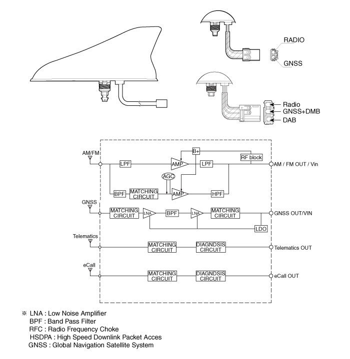
| Components |
Roof Antenna. Repair procedures
| Removal |
| 1. |
Disconnect the negative (-) battery terminal.
|
| 2. |
Remove the rear roof trim.
(Refer to Body - "Roof Trim Assembly")
|
| 3. |
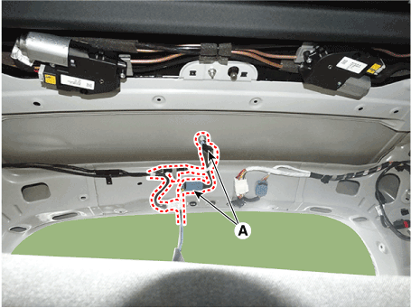
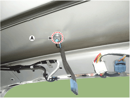
Disconnect the roof antenna connectors (A) from the roof antenna.
|
| 4. |
Remove the roof antenna (A) after removing a nut.
|
| Installation |
| 1. |
Connect the roof antenna connectors.
|
| 2. |
Install the rear roof trim.
|
AVN Keyboard Assembly. Components and components location
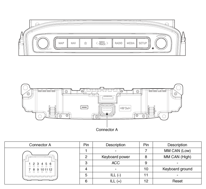
| Components |
AVN Keyboard Assembly. Repair procedures
| Removal |
| 1. |
Disconnct the negative (-) battery terminal.
|
| 2. |
Using a remover, remove the console upper cover (A).
|
| 3. |
Disconnect the console upper cover connector (A).
|
| 4. |
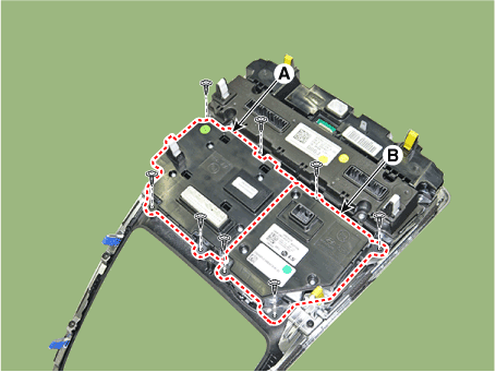
Remove the drive mode unit (A) and SBW switch assembly (B) after loosening
mounting screws.
|
| 5. |
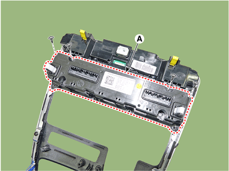
Remove the heater & A/C contorl switch (A).
|
| 6. |
Remove the AVN keyboard assembly (A) after loosening mounting screws.
|
| Installation |
| 1. |
Install the AVN keyboard unit.
|
| 2. |
Install the heater & A/C contorl switch
|
| 3. |
Install the drive mode unit and SBW switch assembly.
|
| 4. |
Install the console upper cover.
|
| 5. |
Connect the negative (-) battery terminal.
|
 Horn
Horn
Components and components location Component Location 1. Horn switch 2. Horn relay (Engine room compartment) 3. Horn (Low pitch) 4. Horn (High pitch) 5. Clock spring Repair procedures Removal 1. Remove ...
 Emergency Call System
Description and operation Description Emergency Call (eCall) When an accident occurs or the user's request is detected, it notifies the call center of the vehicle status using the wireless network ...
See also:
Components and Components Location
Component Location 1. DDM (Driver door module) 2. ADM (Assistant door module) 3. Front window motor 4. Rear window motor 5. Rear window switch ...
Door Scuff Trim. Components and Components Location
Component Location 1. Front door scuff trim 2. Rear door scuff trim ...
Description and Operation
Cruise Control The cruise control system is engaged by the cruise "ON/OFF" main switch located on right of steering wheel column. The system has the capability to cruise, coast, accelerate and ...

