Description and operation
Emergency Call (eCall)
When an accident occurs or the user's request is detected, it notifies the call
center of the vehicle status using the wireless network so that the center can
provide necessary emergency service.
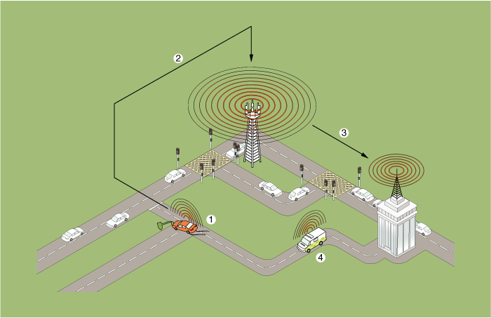
1. Emergency
Call
2. Radio Communication network
|
3. Public-Safety
Answering Point (PSAP)
4. Emergency rescue service
|
eCall Function
|
1. |
Automatic notification function : It detects airbag signal that is triggered
by accident and automatically notifies the call center of the accident.
|
(1) |
An accident occurs (condition : IGN ON)
|
|
(2) |
Collision signal : Sent from the airbag control unit (ACU) to
the eCall unit
|
|
(3) |
Place a call : An emergency call is placed to the most appropriate
public-safety answering point (PSAP).
|
|
(4) |
Transmit MSD : After the call is connected, the Minimum Set
of Data (MSD) is transmitted using the in-band communication
(technology that transmits data through telephone voice channel).
|
|
(5) |
Connect to a call center agent, who in turn provides emergency
service.
|
• |
The eCall system may not work properly if the
vehicle damage is grave or the airbag does not
operate due to a minor accident.
|
|
|
|
|
2. |
Manual notification function : The driver decides to operate the SOS
button to notify the call center of the accident manually.
|
(1) |
The driver decides to operate the SOS button.
|
|
(2) |
Place a call : An emergency call is placed to the most appropriate
PSAP.
|
|
(3) |
Transmit MSD : After the call is connected, the MSD is transmitted
using the in-band communication (technology that transmits data
through telephone voice channel).
|
|
(4) |
Connect to a call center agent, who in turn provides emergency
service.
|
• |
If you want to cancel the connection attempt
while placing a call by pressing the SOS button,
press the button again.
|
|
|
|
Configuration of eCall Controller
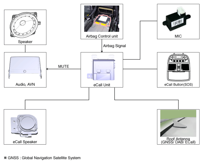
Input button & Indicator
SOS button : Press the button to place a call to the call center.
LED indicator lamp : The red and green LEDs turn on for 3 seconds after the
ACC is on and stay turned off in standby until the key is turned off.
The red LED turns on when there is a problem with the eCall system.
The green LED turns on when the eCall system is operating normally.
Components and components location
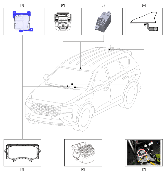
1. Emergency
call unit
2. Emargency call system button
3. Emargency call system MIC
4. Roof antenna
|
5. Head
unit (AVN)
6. Emergency call speaker
7. Supplemental Restraint System Control Module (SRSCM)
|
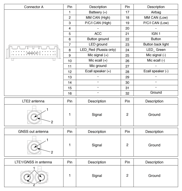
Emergency Call (eCall) Unit. Components and components location
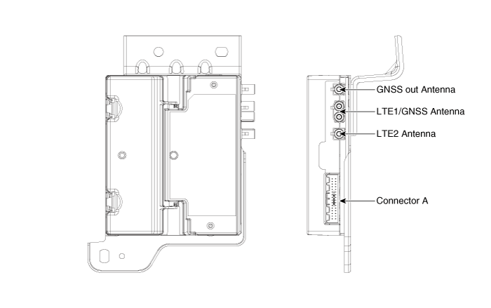
Emergency Call (eCall) Unit. Repair procedures
| •
|
Replace the eCall unit.
|
| •
|
Replace the Back-up Battery (BUB).
|
| •
|
Replace the eCall speaker and MIC.
|
| •
|
Replace the eCall antenna and Roof antenna.
|
|
|
1. |
Disconnect the negative (-) battery terminal.
|
|
2. |
Remove the crash pad cnter panel.
(Refer to Body - "Crash Pad Center Panel")
|
|
3. |
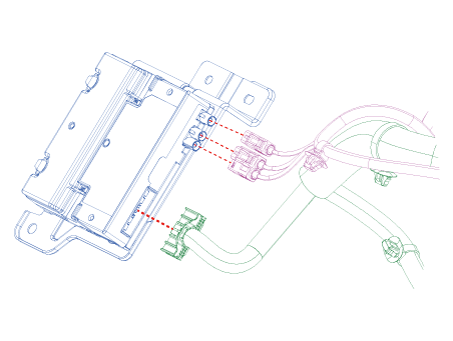
Disconnect ecall unit connectors.
|
|
4. |
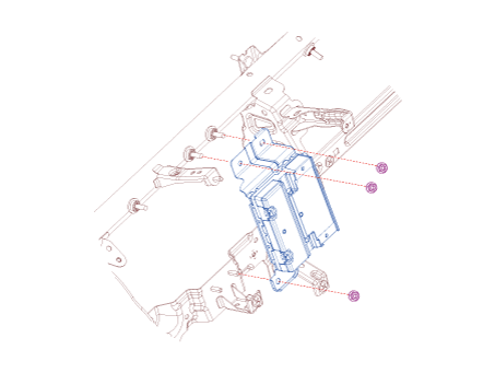
Remove the ecall unit after loosening mounting nuts.
|
e-Call Unit Back Up Battery
|
1. |
Disconnect the negative (-) battery terminal.
|
|
2. |
Remove the eCall Unit.
|
|
3. |
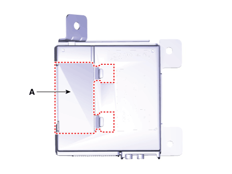
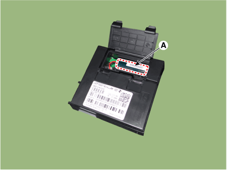
If it is necessary to replace the back-up battery, remove the back-up
battery cover (A).
|
|
4. |
Replace the back-up battery (A).
|
|
If RED LED is on, check the eCall system with the diagnostic tools.
| –
|
Replace the eCall unit.
|
| –
|
Replace the Back-up Battery (BUB).
|
| –
|
Replace the eCall speaker and MIC.
|
| –
|
Replace the eCall antenna and Roof antenna.
|
|
eCall Unit
|
1. |
Install the eCall unit.
|
|
2. |
Install the crash pad center panel.
|
|
3. |
Connect the negative (-) battery terminal.
|
|
4. |
Perform the "eCall Parameter Download"
(Refer to Inspection - " Inspection with Diagnostic Tools")
|
Inspecting Back-Up Battery
Back-up battery (BUB) embedded in the eCall system has a finite lifespan and
using it for a long time may decrease its charging/discharging performance.
The back-up battery guarantees the operation of the eCall system when the vehicle
battery cannot be used due to an accident. Be sure to inspect the back-up battery
if the red LED turns on and replace it if necessary.
| •
|
Refer to the owner's manual for the Back-Up Battery (BUB) replacement
cycle.
|
|
| •
|
The eCall system is aimed to place an urgent call to the call
center during an emergency. Arbitrarily removing or operating
the system components may affect the safety of people and may
result in false notification of an accident to the emergency
call center.
|
|
| •
|
The red LED turns on when there is a problem with the eCall
system.
|
| •
|
If one or more DTCs for the eCall system are issued, check the
eCall system(Unit, Button(Built in overhead console), Speaker,
Antenna) by diagnostic tools.
|
|
Inspection with Diagnostic Tools
In the eCall system, failure can be quickly diagnosed by using the vehicle diagnostic
system.
The diagnostic system provides the following information.
| 1) |
Self diagnosis : Checking failure and code number (DTC)
|
| 2) |
Current data : Checking the system input/output data state
|
|
1. |
Select the "Car Model" and the "eCall System" to be checked in order
to check the vehicle with the tester.
|
|
2. |
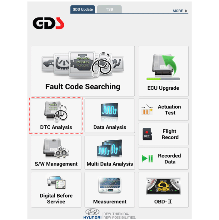
To inquire the cause of trouble for each module by self diagnosis, select
'Diagnostic Trouble Code'.
|
|
3. |
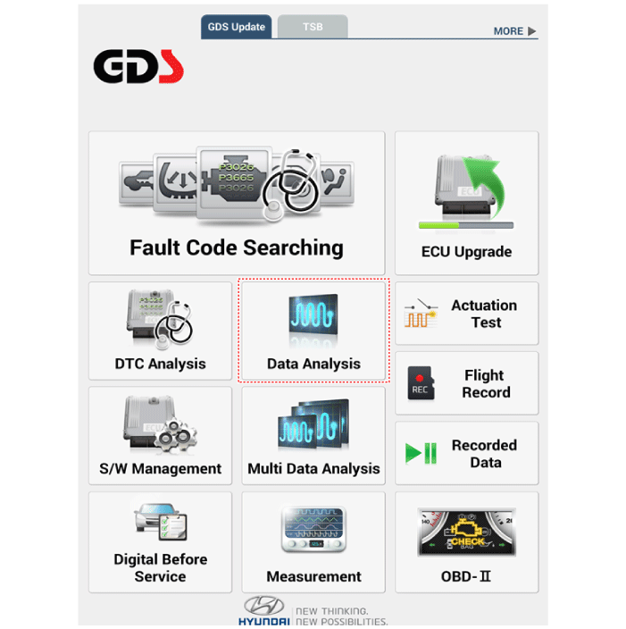
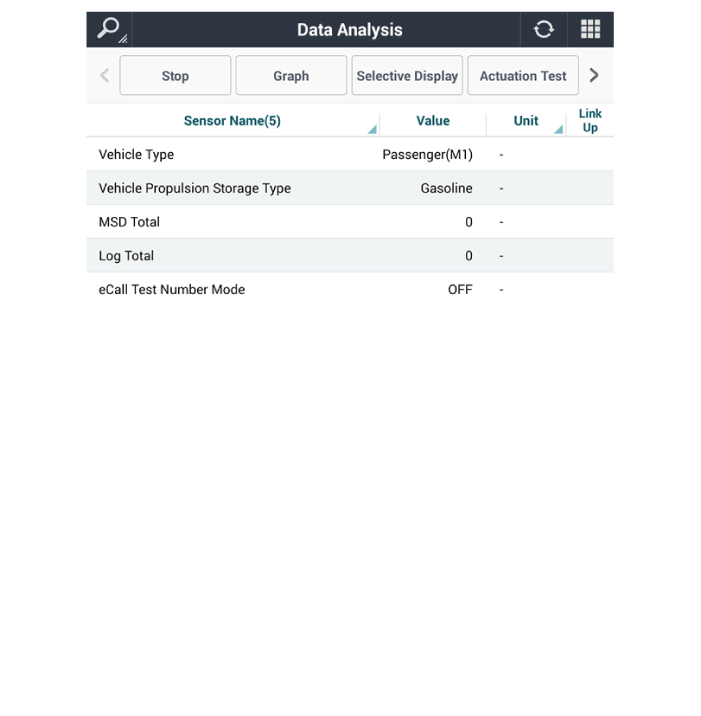
Select the 'Current Data' menu to check the current state of the input/output
data.
|
eCall System Reset
The eCall System Reset function is to reset when eCall is locked or stopped.
| •
|
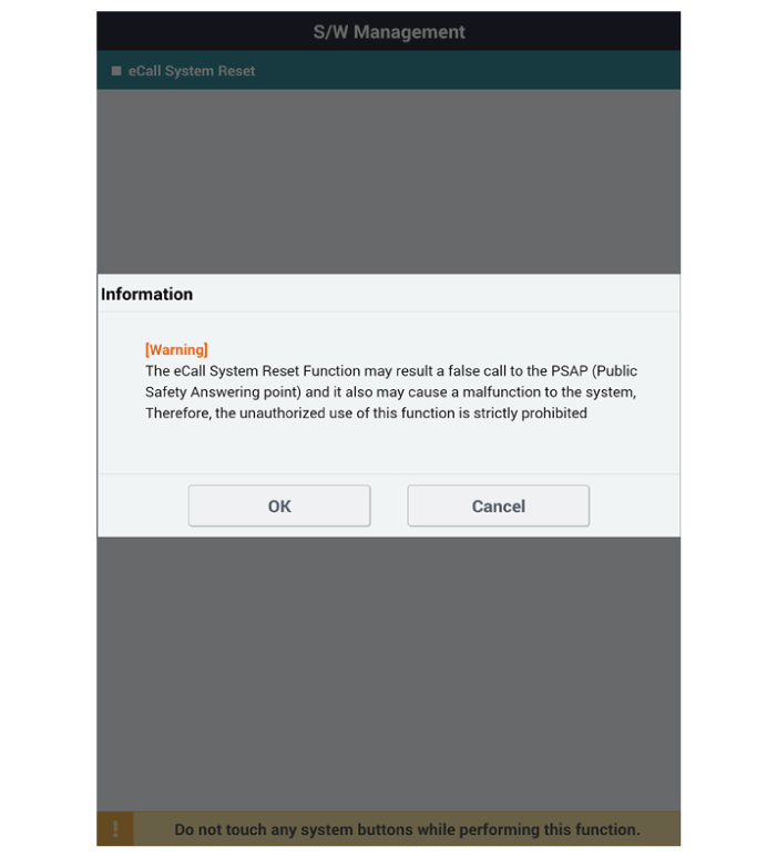
The eCall System Reset function may result a faise call to the
PSAP (Public Safety Answering point) and it also may cause a
malfunction to the system, therefore, the unauthorized use of
this function is strictly prohibited.
|
|
|
1. |
Turn the ignition switch OFF.
|
|
2. |
Connect the diagnostic tools.
|
|
3. |
Turn the ignition switch ON without the engine running.
|
|
4. |
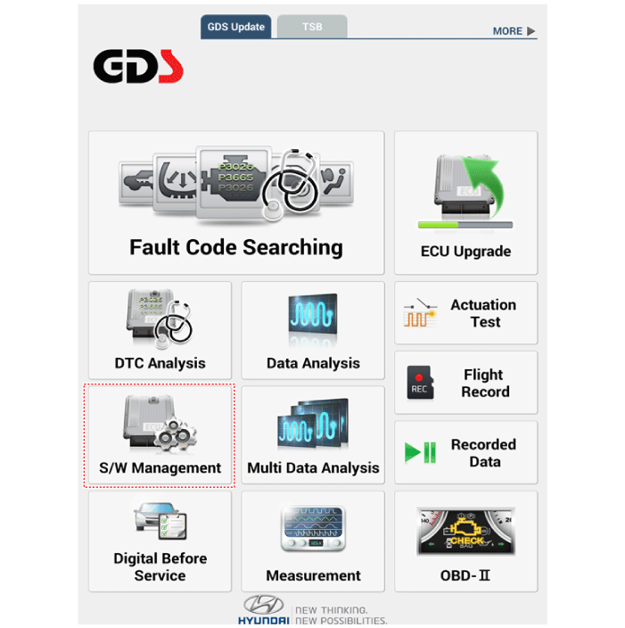
Select the "Car Model" and "S/W Management".
|
|
5. |
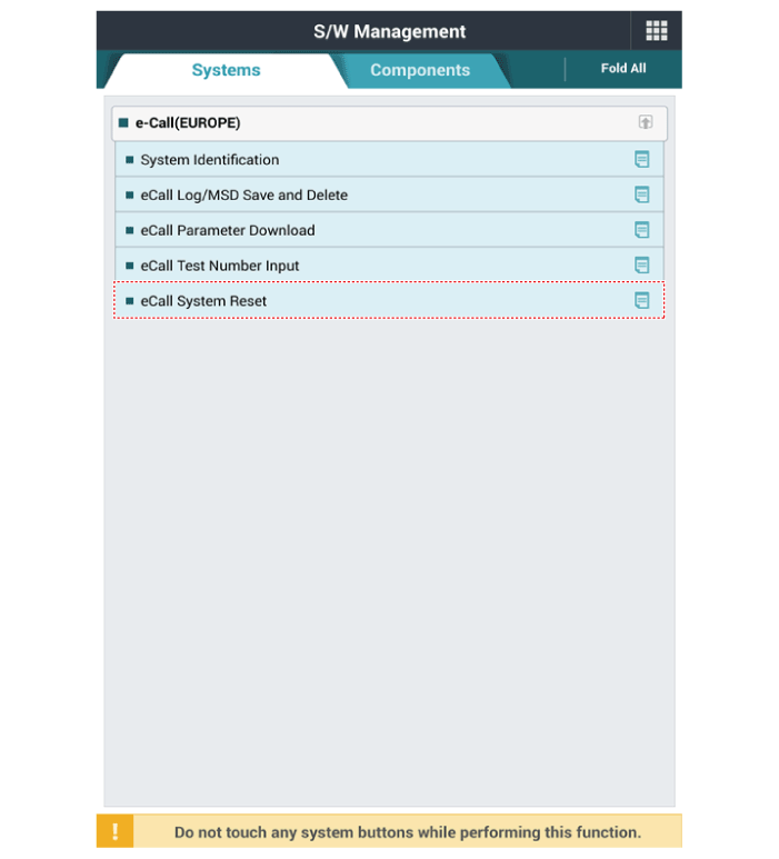
Select the "eCall System Reset"
|
|
6. |
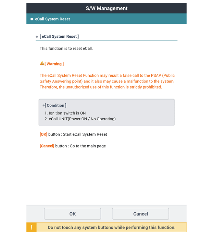
Follow the screen instructions to perform the "eCall System Reset".
|
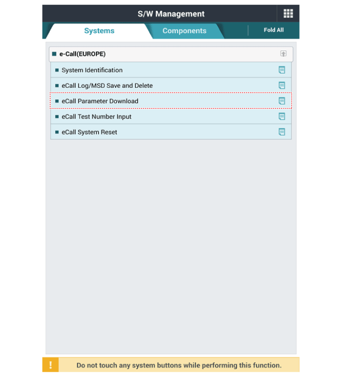
eCall Parameter Download
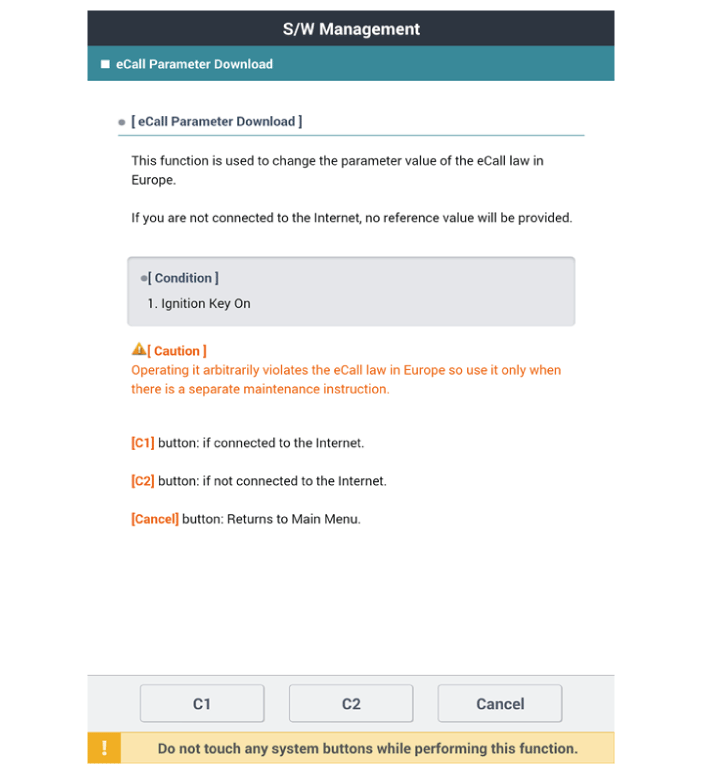
eCall Parameter Download is used to change the parameter value of the eCall
law in Europe.
|
1. |
Turn the ignition switch OFF.
|
|
2. |
Connect the diagnostic tools.
|
|
3. |
Turn the ignition switch ON without the engine running.
|
|
4. |
Select the "Car Model" and "S/W Management".

|
|
5. |
Select the "eCall Parameter Download"
|
|
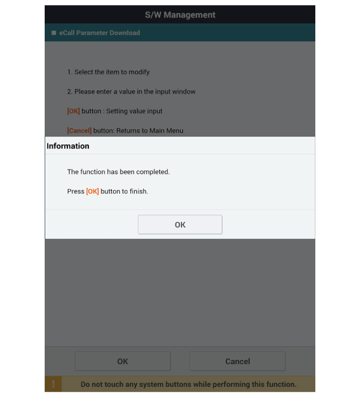
6. |
Follow the screen instructions to perform the "eCall Parameter Download".
|
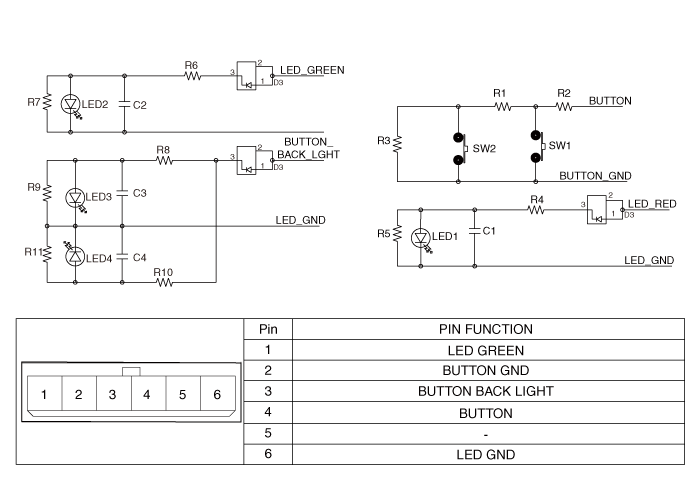
Emergency Call (eCall) Button. Schematic diagrams
eCall switch (1B)
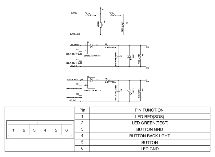
eCall switch (2B)
Emergency Call (eCall) Button. Repair procedures
|
1. |
Disconnect the negative (-) battery terminal.
|
|
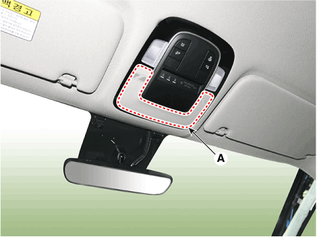
2. |
Remove the overhead console cover (A).
|
|
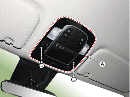
3. |
Remove the overhead console (A) after loosening mounting screws.
|
|
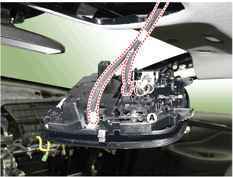
4. |
Remove the overhead console after disconnecting the connector (A).
|
|
1. |
Install the overhead console after connecting the connector.
|
|
2. |
Connect the negative (-) battery terminal.
|
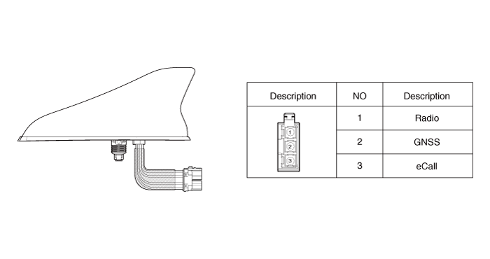
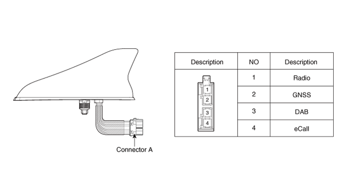
Emergency Call (eCall) Antenna. Components and components location
RADIO+GNSS+eCall
RADIO+GNSS+DAB+eCall
Emergency Call (eCall) Antenna. Repair procedures
eCall Antenna
|
1. |
Disconnect the negative (-) battery terminal.
|
|
2. |
Remove the roof trim assembly.
(Refer to Body - "Roof Trim Assembly")
|
|
3. |
Disconnect the eCall antenna cable and connector (A) and then remove
the antenna mounting nut.
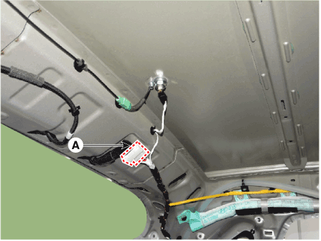
|
eCall Anenna
|
1. |
Connect the eCall antenna connectors.
|
|
2. |
Install the roof trim assembly.
|
• |
Make sure that the cables and connectors are plugged
in properly.
|
|
• |
Check the Ecall system.
|
|
|
Emergency Call (eCall) Speaker. Repair procedures
|
1. |
Disconnect the negative (-) battery terminal.
|
|
2. |
Remove the crash pad lower panel.
(Refer to Body - "Crash Pad Lower Panel")
|
|
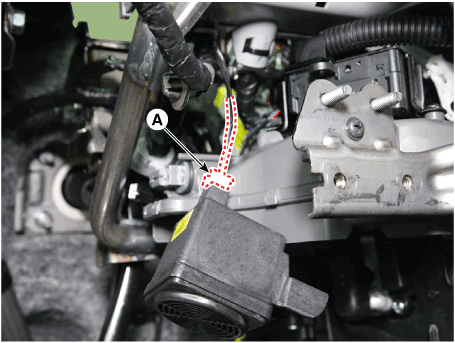
3. |
Remove the ecall speaker (A).
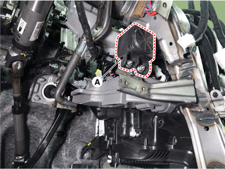
|
|
4. |
Remove the ecal speaker after disconnecting speaker connector (A).
|
|
1. |
Install the speaker and connect the speaker connector.
|
|
2. |
Install the glove box housing cover.
|
|
3. |
Connect the negative (-) battery terminal.
|
Description and operation Description AVN system The AVN system has improved information search and easiness of manipulation for the driver by simplifying the system operation experience and unifying the ...
Description and operation Description The SMART KEY system is a system that allows the user to access and operate a vehicle in a very convenient way. To access the vehicle, no traditional key or remote ...
See also:
Specifications
Specifications Smart Key Unit Items Specification Rated voltage DC 12V Operating voltage DC 9 ~ 16V Operating temperature -22°F ~ 167°F (-30°C ~ 75°C) Load Max. 2.9mA (When welcome light function off) ...
LCD display control
The LCD display modes can be changed by using the control buttons. Information When the infotainment system is applied, only the User’s Setting mode on the infotainment system is supported but the User’s ...
Specifications
Specifications Front Suspension Item Specification Suspension type Macpherson Strut Shock absorber Type Gas Stabilizer Bar Coil spring Free Height [I.D. color] 2WD 330.0 mm(12.9921 in.), [White / ...
 Hyundai Santa Fe (TM): Emergency Call System


 AVN System
 Smart Key System


