 Hyundai Santa Fe (TM): Button Engine Start System
Description and operation
| Description |
| – |
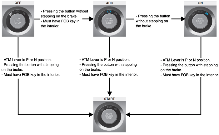
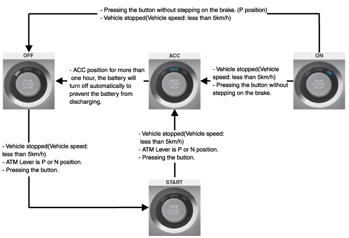
Changing the state of engine ignition and power by using the start button.
|
| – |
Controlling external relays for ACC / IGN1 / IGN2 terminal switching
and STARTER, without use of mechanical ignition switch.
|
| – |
Indicating the vehicle status on display by using LED or explicit messages.
|
| – |
Immobilizer function by LF transponder communication between fob and
fob holder.
|
| – |
Redundant architecture for high system dependability .
|
| – |
Interface with Low Speed CAN vehicle communication network.
|
| – |
Interface with LIN vehicle communication network depending on platform
.
|
| – |
Switching of ACC / IGN1 / IGN2 terminals.
|
| – |
Control of the STARTER relay BAT line (high side) based on communication
with EMS ECU.
|
| – |
Management of the Immobilizer function.
|
| – |
Management of BES warning function.
|
| • |
Control Ignition and engine ON/OFF by Sending signal to IPM.
|
| • |
Display status by LED Lamp ON/OFF. (Amber or Green)
|
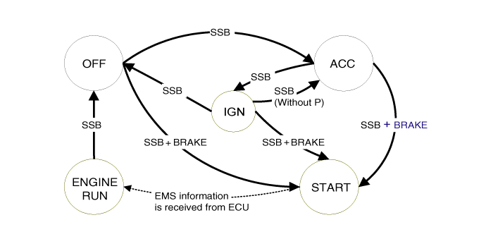
| 1. |
Electric power ON / Ignition ON
|
| 2. |
Electric power OFF/ Ignition OFF
|
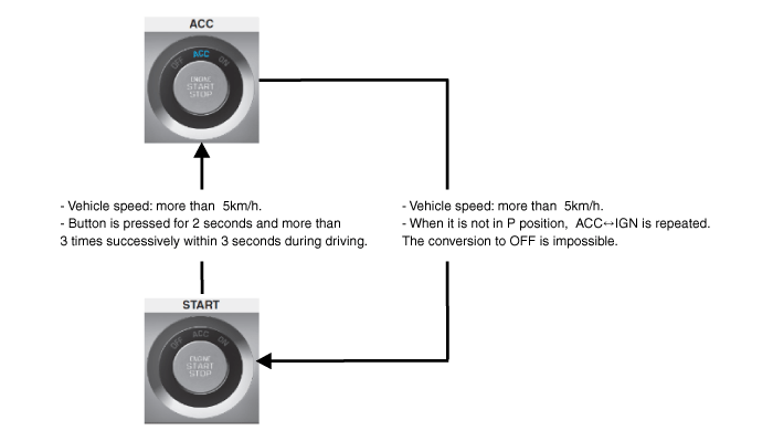
| 3. |
How to off the ignition forcibly and to restart during driving
|
| 4. |
Function of 0.5 second delay for brake switch input.
The starting is available when the brake pedal is stepped on within
0.5 second after pressing the start button in engine OFF state.
|
| 5. |
State of start button indicator (LED) ON depending on the electric power
state.
|
| • |
"Start Stop Button (SSB) monitoring",
|
| • |
"Immobilizer communication" (with Engine Management System unit for
immobilizer release),
|
| • |
"Authentication server" (Validity of Transponder and in case of Smart
Key option Passive Fob authentication ),
|
| • |
"System consistency monitoring",
|
| • |
"System diagnosis",
|
| • |
Control of display message / warning buzzer .
|
| • |
Control of Terminal relays
|
| • |
Monitoring of the Vehicle speed received from sensor or ABS/ESP ECU.
|
| • |
Control of SSB LEDs (illumination, clamp state).
|
| • |
Control of the base station located in SSB through direct serial interface.
|
| • |
System consistency monitoring to diagnose SMK failure and to switch
to relevant limp home mode.
|
| • |
Providing vehicle speed information
|
| • |
Start Stop Button (SSB) monitoring
|
| • |
Starter power control
|
| • |
To activate the power modes ‘Off’, ’Accessory’, ‘Ignition’ and 'Start'
by switching the corresponding terminals
|
| • |
To start the engine
|
| • |
To stop the engine
|
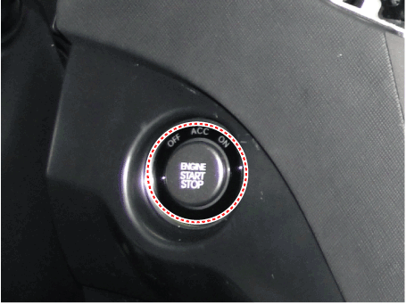
|
System State |
Terminal Status |
Engine status |
|
1. OFF - Locked |
OFF |
Stopped |
|
2. OFF - Unlocked |
OFF |
Stopped |
|
3. ACC |
ACC |
Stopped |
|
4. IGN |
IGN1, IGN2, ACC |
Stopped |
|
5. Start |
IGN1, Start |
Cranking |
|
6. IGN - Engine |
IGN1, IGN2, ACC |
Running (means "self-running") |
|
System State |
Terminal Status |
Engine status |
|
1. OFF - UNLOCKED |
OFF |
Stopped |
|
2. ACC |
ACC |
Stopped |
|
3. IGN |
IGN1, IGN2, ACC |
Stopped |
|
4. Start |
IGN1, START with special pattern of activation |
Cranking |
|
5. IGN - Engine |
IGN1, IGN2, ACC |
Running (means "self-running") |
Components and components location
| Component Location |
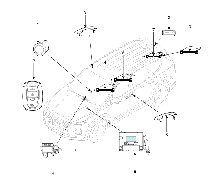
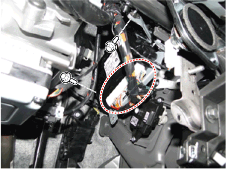
| 1. Start Stop
Button(SSB) 2. FOB key 3. Tailgate open switch 4. Interior antenna 1 5. Interior antenna 2 |
6. Intergrated
Body Control Unit (IBU) 7. Trunk antenna 8. Door handle & door antenna 9. Bumper antenna |
Start/Stop Button. Components and components location
| Component |
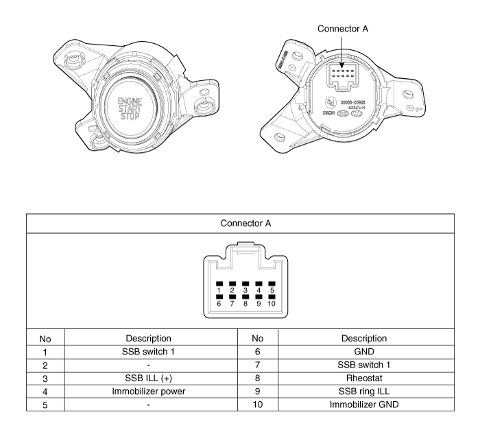
Start/Stop Button. Repair procedures
| Removal |
| 1. |
Disconnect the negative (-) battery terminal.
|
| 2. |
Remove the driver crash pad lower panel.
(Refer to Body - "Crash Pad Lower Panel")
|
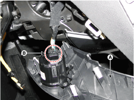
| 3. |
Disconnect the start/stop button connector (B) after removing the center
fascia garnish (A).
|
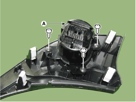
| 4. |
Remove the start/stop button (A) after removing the screws (3EA).
|
| Installation |
| 1. |
Install the start/stop button.
|
| 2. |
Install the crash pad lower panel.
|
| 3. |
Connect the negative (-) battery terminal.
|
Ignition Switch Assembly. Repair procedures
| Inspection |
| 1. |
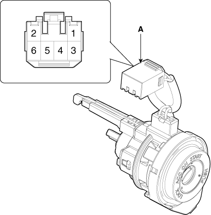
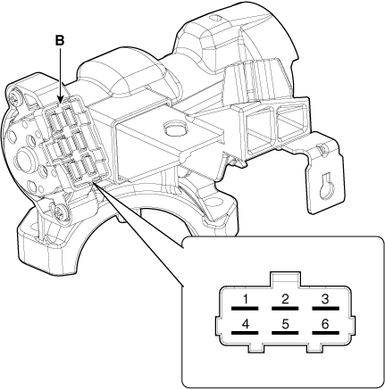
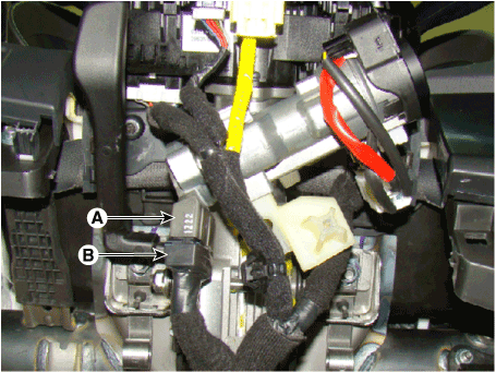
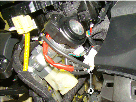
Disconnect the ignition switch connector (B) and key warning switch
connector (A) from under the steering column.
|
| 2. |
Check for continuity between the terminals.
|
| 3. |
If continuity is not specified, replace the switch.
|

| Removal |
| 1. |
Disconnect the negative (-) battery terminal.
|
| 2. |
Remove the crash pad lower panel.
(Refer to Body - "Crash Pad Lower Panel")
|
| 3. |
Remove the steering column upper and lower shrouds.
(Refer to Body - "Steering Column Shroud Panel")
|
| 4. |
Remove the ignition switch (A) after disconnecting the 6P connector
(B).
|
| 5. |
Remove the key warning and immobilizer connector (A).
|
| 6. |
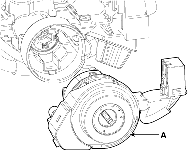
If it is necessary to remove the key lock cylinder (A), remove the key
lock cylinder with key ACC.
|
| Installation |
| 1. |
Install the key lock cylinder.
|
| 2. |
Install the key warning and immobilizer connector.
|
| 3. |
Install the ignition switch.
|
| 4. |
Install the steering column shrouds and crash pad lower panel.
|
 Immobilizer System
Description and operation Description The immobilizer system will disable the vehicle unless the proper ignition key is used, in addition to the currently available anti-theft systems such as car alarms, ...
 AC Inverter System
Description and operation Description An inverter is a device that transforms the DC voltage from the battery into an AC voltage (220 V). The inverter can power various electrical devices that consume ...
See also:
Panorama Sunroof
Components and components location Component Location 1. Panorama sunroof 2. Panorama sunroof switch 3. Panorama sunroof motor & controller 4. Roller blind motor & slave controller Schematic diagrams ...
Exhaust Manifold. Repair procedures
Removal and Installation 1. Remove the engine cover. 2. Disconnect the battery negative terminal. 3. Disconnect the front oxygen sensor connector (A) and the rear oxygen sensor connector (B). 4. Remove ...
Spark Plug. Repair procedures
Inspection [On vehicle inspection] 1. Accelerate the engine to about 3,000 rpm 3 times or more. 2. Remove the spark plug. 3. Check the spark plug visually. If the electrode is dry, the spark plug is normal. ...

