 Hyundai Santa Fe (TM): Panorama Sunroof
Components and components location
| Component Location |
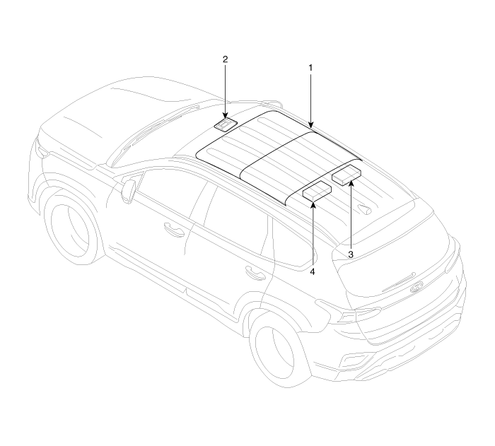
| 1. Panorama sunroof 2. Panorama sunroof switch |
3. Panorama sunroof
motor & controller 4. Roller blind motor & slave controller |
Schematic diagrams
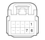
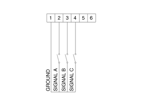
| Circuit Diagram |
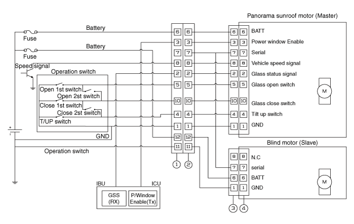
|
No |
Wire harness connector |
Panorama motor |
Blind motor |
|
|
|
|
|
|
1 |
Ground 1 |
Ground 1 |
Ground 2 |
|
2 |
Glass status signal / Tool fot glass |
Glass status signal/ Tool (Parameter) |
- |
|
3 |
Power window enable |
Power window enable |
- |
|
4 |
Tilu up switch |
Tilu up switch |
- |
|
5 |
OPEN switch |
OPEN switch |
- |
|
6 |
Battery 1 (+) |
Battery 1 (+) |
Battery2 (+) |
|
7 |
Serial |
Serial |
Serial |
|
8 |
Vehicle speed signal |
Vehicle speed signal |
- |
|
9 |
- |
Glass open switch |
- |
|
10 |
Glass close switch |
Glass close switch |
- |
|
11 |
GND 2 |
  |
  |
|
12 |
Battery2 (+) |
Panorama Sunroof Switch. Repair procedures
| Inspection |
| 1. |
Disconnect the negative (-) battery terminal.
|
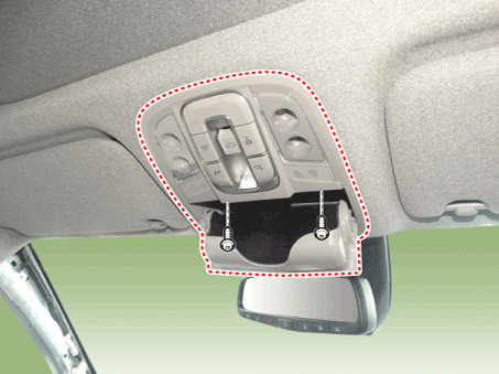
| 2. |
Open the sunglass case cover from the overhead console then remove screws
(2EA).
|
| 3. |
Check for continuity between the terminals. If the continuity is not
as specified, replace the panoramaroof switch.
|

Panorama Sunroof Motor. Repair procedures
| Replacement |
| 1. |
Disconnect the negative (-) battery terminal.
|
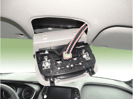
| 2. |
Remove the roof trim assembly.
(Refer to Body - "Roof Trim Assembly")
|
| 3. |
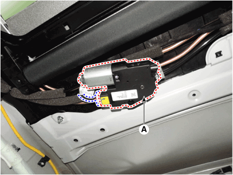
Remove the panoramaroof motor mounting screws (3EA). And then remove
the panoramaroof motor (A) after disconnecting the connector.
[Glass Motor]
|
| 4. |
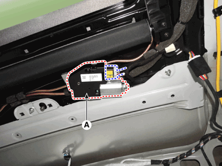
Remove the panoramaroof motor mounting screws (3EA). And then remove
the panoramaroof motor (A) after disconnecting the connector.
[Blind Motor]
|
You need to reset the sunroof motor to its default settings for the
following cases :
|

| 1. |
Turn the ignition key to the ON position and then close the panoramaroof
completely.
|
| 2. |
Release the panoramaroof control lever.
|
| 3. |
Press and hold the CLOSE button for more than 10 seconds until the sunroof
has moved slightly.
|
| 4. |
Release the panoramaroof control lever.
|
| 5. |
Press and hold the CLOSE button once again within 5 seconds until the
panorama sunroof do as follows ;
|
| 6. |
Reset procedure of panorama system is finished.
|
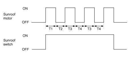
| 1. |
The panoramaroof ECU detects the Run- time of motor
|
| 2. |
Motor can be operated continuously for the 1st Run-time(120 ± 10sec.).
|
| 3. |
Motor which is operated continuously stops operating after the 1st Run-time(120
± 10sec.).
|
| 4. |
And then Motor is not operated for the 1st Cool-time(18 ± 2sec.).
|
| 5. |
Motor is operated for the 2nd Run-time(10 ± 2sec.) at the continued
motor operation after 1st Cool-time(18 ± 2sec.)
|
| 6. |
Motor which is operated continuously stops operating after the 2nd Run-time(10
± 2sec.)
|
| 7. |
Motor is not operated for the 2nd Cool-time(18 ± 2sec.).
|
| 8. |
Motor repeats the 2nd Run-time and 2nd Cool-time at the continued motor
operation.
T1 : 120 ± 10 sec., T2 : 18 ± 2 sec.,
T3 : 10 ± 2 sec., T4 : 18 ± 2 sec.
|
 Electro Chromic Inside Rear View Mirror
Description and operation Description The ECM (Electro Chromatic inside rear view Mirror) is intended dim the reflecting light in the rear view mirror. The forward facing sensor detects brightness of the ...
 Lighting System
Components and components location Component Location 1. Head lamp (Low) 2. Head lamp (High) 3. Daytime running light (DRL)/Positioning lamp 4. Turn signal lamp 5. Head lamp (ADD Low) 6. Side repeater ...
See also:
Tail Gate
Repair procedures Adjustment 1. Place the car on a flat surface and check whether the body and trunk lid are well-aligned. 2. After loosening the tailgate hinge (A) mounting bolt, adjust the tailgate by ...
Automatic Transaxle. Components and Components Location
Components Location 1. Automatic transaxle 2. Shift cable bracket 3. Inhibitor switch connector 4. Manual control lever 5. Automatic transaxle mounting support bracket 6. Solenoid valve connector 7. ATF ...
Ignition Coil. Repair procedures
Removal 1. Disconnect the battery nagative terminal. 2. Remove the engine cover. 3. Disconnect the ignition coil connector (A). • When removing the ignition coil connector, pull the lock pin (A) and ...
