 Hyundai Santa Fe (TM): Front Hub / Knuckle / Tone Wheel
Components and components location
| Components |

|
1. Front knuckle 2. Dust cover |
3. Front hub assembly 4. Front brake disc |
Repair procedures
| Removal |
|
| 1. |
Loosen the wheel nuts slightly.
Raise the vehicle, and make sure it is securely supported.
|
| 2. |
Remove the front wheel and tire (A) from the front hub.
|
| 3. |
Remove the front brake caliper.
(Refer to Brake System - "Front Disc Brake")
|
| 4. |
Loosen the screw and then remove the front disc (A).
|
| 5. |
Remove the dust cover (A).
|
| 6. |
Remove the wheel speed sensor (A) from the knuckle after loosening the
mounting bolt.
|
| 7. |
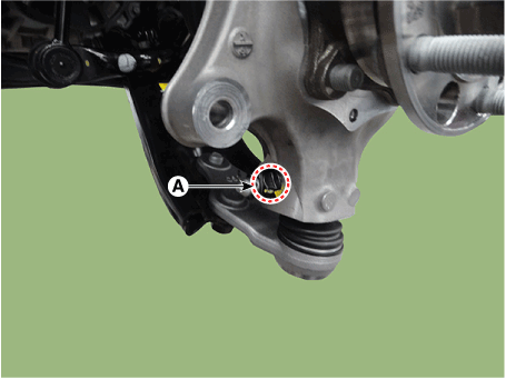
Remove the split pin and nut (A).
|
| 8. |
Remove the lower arm from the knuckle by using the SST (09568-4R100).
|
| 9. |
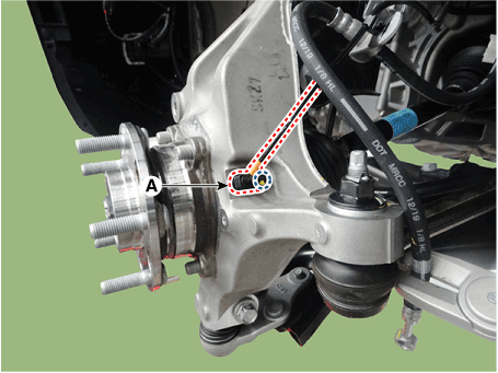
Remove the split pin and nut (A).
|
| 10. |
Remove the tie rod end ball joint (A) using the SST (09568-2J100).
|
| 11. |
Remove the front strut assembly mounting bolts and nuts (A) from the
front axle.
|
| 12. |
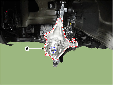
Remove the front knuckle & front hub bearing (A) after loosening the
caulking nut.
|
| 13. |
Remove the front hub bearing from the front knuckle after loosening
the mounting bolts (A).
|
| Inspection |
| 1. |
Check the hub for cracks and the splines for wear.
|
| 2. |
Check the brake disc for scoring and damage.
|
| 3. |
Check the knuckle for cracks.
|
| 4. |
Check the bearing for cracks or damage.
|
| Installation |
| 1. |
To install, reverse the removal procedures.
|
| 2. |
Check the alignment.
(Refer to Suspension System - "Alingment")
|
 Special service tools
Special Service Tools Tool(Number and Name) Illustration Use Ball joint puller 09568-2J100 Use for removal of ball joint Lower arm ball joint remover 09568-4R100 Removal of the lower arm ball joint. Band ...
 Driveshaft Assembly
Front Driveshaft. Components and components location Components 1. Front driveshaft (LH) 2. Inner shaft bearing bracket 3. Front driveshaft (RH) Front Driveshaft. Repair procedures Removal ...
See also:
Panoramic sunroof
If your vehicle is equipped with a sunroof, you can slide or tilt your sunroof with the sunroof control lever located on the overhead console. The sunroof can only be opened, closed, or tilted when the ...
AC Inverter System
Description and operation Description An inverter is a device that transforms the DC voltage from the battery into an AC voltage (220 V). The inverter can power various electrical devices that consume ...
Rear Differential Carrier. Components and Components Location
Component 1. Rear Differential Carrier 2. Coupling Assembly ...


