 Hyundai Santa Fe (TM): Front Seat
Front Seat Assembly. Components and components location
| Component Location |
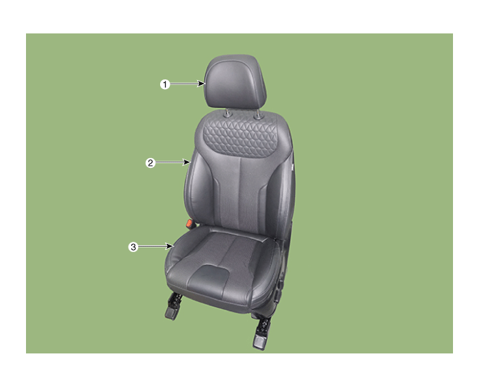
| 1. Front seat
headrest 2. Front seat back cover |
3. Front seat
cushion cover |
Front Seat Assembly. Repair procedures
| Replacement |
| 1. |
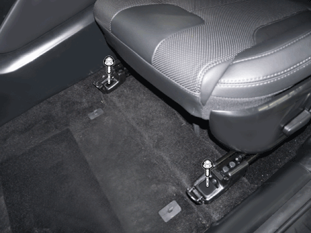
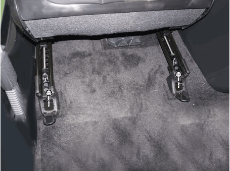
Open the cover and loosen the front seat mounting bolts.
[Front]
[Rear]
|
| 2. |
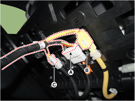
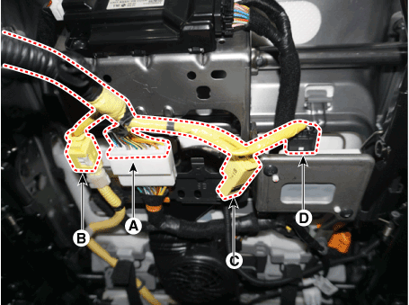
Separate the main connector (A) , side airbag connector (B) , front
seat belt buckle connector (C) and OCS connector (D).
[Driver's]
[Passenger's]
|
| 3. |
To install, reverse removal procedure.
|
Front Seat Shield Outer Cover. Components and components location
| Component Location |
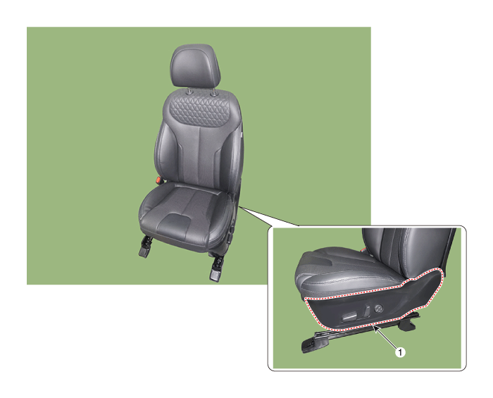
| 1. Front seat
shield outer cover |
Front Seat Shield Outer Cover. Repair procedures
| Replacement |
|
|
| 1. |
Remove the front seat assembly.
(Refer to Front Seat - "Front Seat Assembly")
|
| 2. |
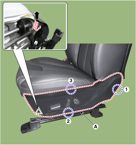
Using a screwdriver and remove the forward cover.
|
| 3. |
Remove the front seat outer shield cover.
|
| 4. |
Separate the front seat power swich connector (A).
|
| 5. |
To install, reverse removal procedure.
|
Front Seat Shield Inner Cover. Components and components location
| Component Location |
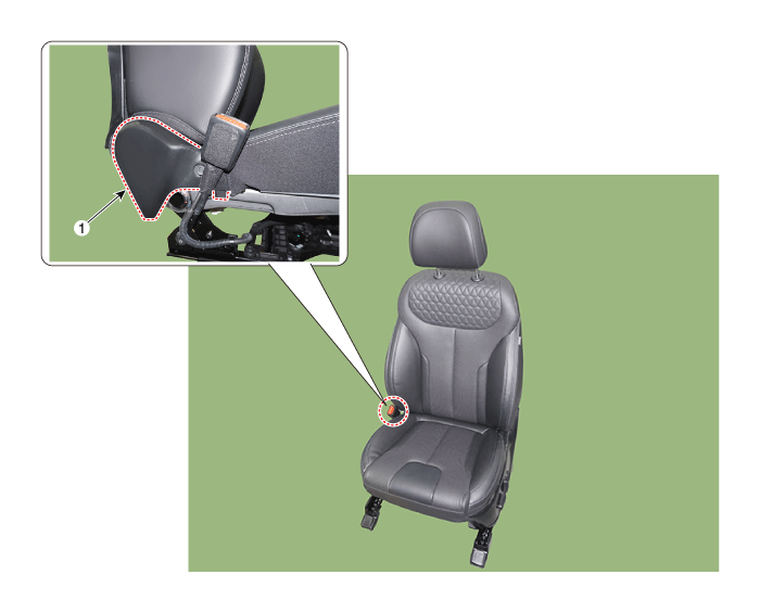
| 1. Front seat
shield inner cover |
Front Seat Shield Inner Cover. Repair procedures
| Replacement |
|
|
| 1. |
Remove the front seat assembly.
(Refer to Front Seat - "Front Seat Assembly")
|
| 2. |
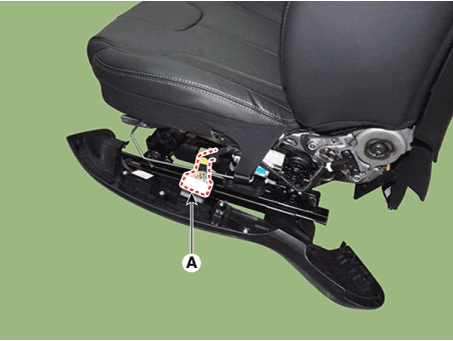
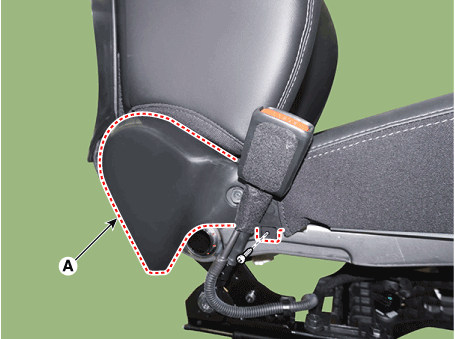
Using a screwdriver or remover, remove the rear hook and remove the
front seat shield inner cover (A).
|
| 3. |
To install, reverse removal procedure.
|
Front Seat Back Cover. Components and components location
| Component Location |
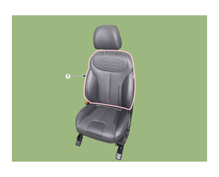
| 1. Front seat
back cover |
Front Seat Back Cover. Repair procedures
| Replacement |
|
|
| 1. |
Remove the front seat assembly.
(Refer to Front Seat - "Front Seat Assembly")
|
| 2. |
Remove the front seat shield outer cover.
(Refer to Front Seat - "Front Seat Outer Shield Cover")
|
| 3. |
Remove the front seat shield inner cover.
(Refer to Front Seat - "Front Seat Inner Shield Cover")
|
| 4. |
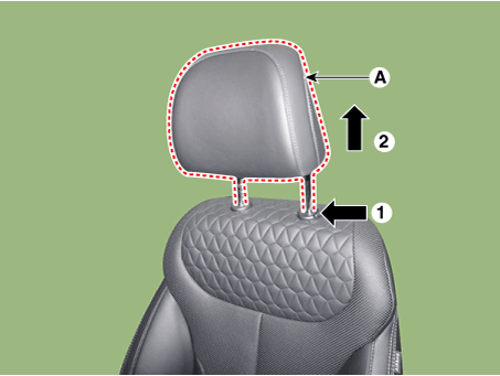
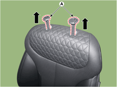
Push the lock pin, remove the front seat headrest (A).
|
| 5. |
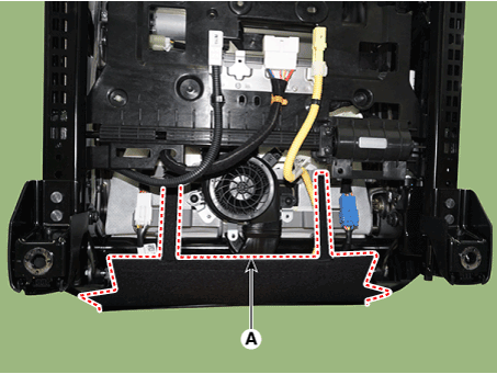
Remove the front seat lower protector (A).
|
| 6. |
Remove the front seat back board (A).
|
| 7. |
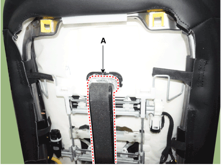
Remove the front seat back duct (A).
|
| 8. |
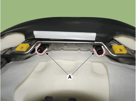
Turn the front seat back cover inside out. Then pull out the headrest
guides (A) while pinching both side of the lower part of the guides,
and remove them.
|
| 9. |
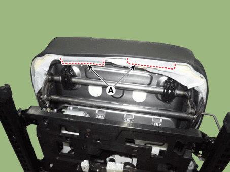
Remove the protector (A) from the front seat back frame.
|
| 10. |
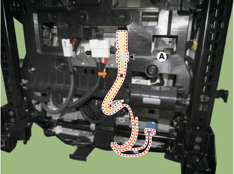
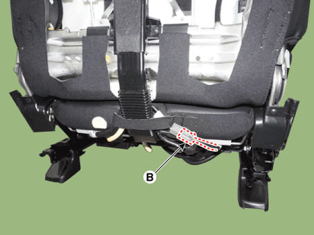
Separate the front seat airbag wiring (A) and seat back heater connector
(B).
|
| 11. |
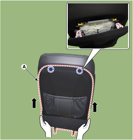
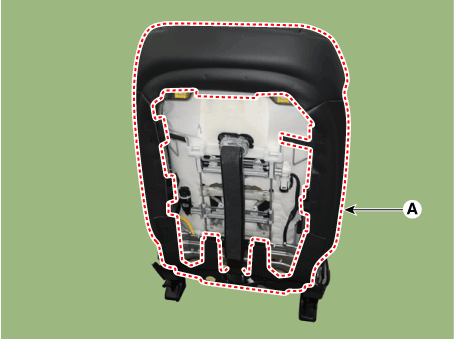
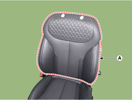
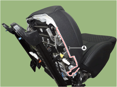
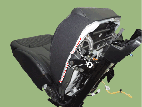
Remove the front seat back cover assembly (A) from the front seat back
frame.
|
| 12. |
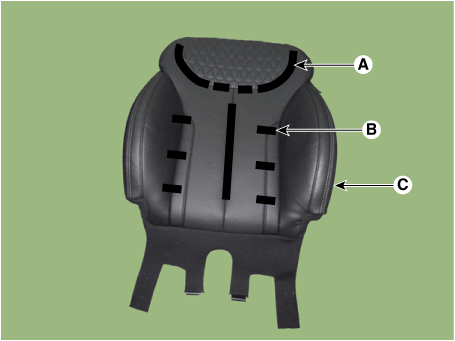
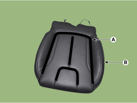
After removing the Velcro tape (A) and tie-down clips (B) inside the
front seat back cover, remove the seat back cover (C).
|
| 13. |
To install, reverse removal procedure.
|
Front Seat Cushion Cover. Components and components location
| Component Location |
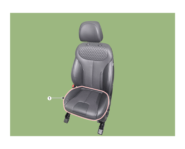
| 1. Front seat
cushion cover |
Front Seat Cushion Cover. Repair procedures
| Replacement |
|
|
| 1. |
Remove the front seat assembly.
(Refer to Front Seat - "Front Seat Assembly")
|
| 2. |
Remove the front seat shield outer cover.
(Refer to Front Seat - "Front Seat Outer Cover")
|
| 3. |
Remove the front seat shield inner cover.
(Refer to Front Seat - "Front Seat Inner Cover")
|
| 4. |
Remove the front seat lower protector (A).
|
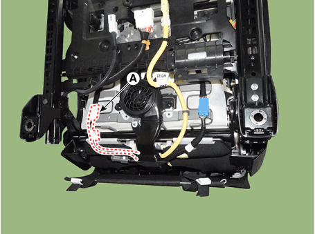
| 5. |
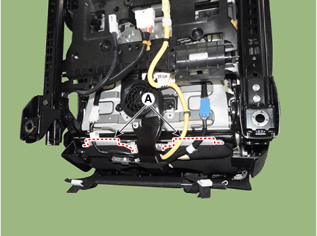
Remove the protector (A) from the front seat cushion frame.
[Lower]
[Upper]
[LH]
[RH]
|
| 6. |
Press the lock pin and separate the front seat heater connector (A).
|
| 7. |
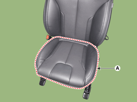
Remove the front seat cushion cover (A) from the front seat cushion
frame.
|
| 8. |
After removing the Velcro tape (A) inside the front seat cushion cover,
remove the seat cushion cover (B).
|
| 9. |
To install, reverse removal procedure.
|
Front Seat Frame Assembly. Components and components location
| Component Location |
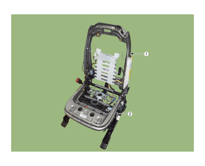
| 1. Front seat
back frame assembly |
2. Front seat
cushion frame assembly |
Front Seat Frame Assembly. Repair procedures
| Replacement |
|
|
| 1. |
Remove the front seat back cover.
(Refer to Front Seat - "Front Seat Back Cover")
|
| 2. |
Remove the front seat cushion cover.
(Refer to Front Seat - "Front Seat Cushion Cover")
|
| 3. |
Remove the SAB module.
(Refer to Restraint - "Side Airbag (SAB) Module")
|
| 4. |
Remove the lumber support assembly.
(Refer to Body Electrical System - "Lumber Support Unit")
|
| 5. |
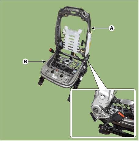
After loosening the mounting bolts, detach the front seat back frame
assembly (A) from the front seat cushion frame assembly (B).
|
| 6. |
To install, reverse removal procedure.
|
 Rear Bumper
Components and components location Components 1. Rear Bumper Side Under Cover 2. Rear Bumper Side Bracket 3. Rear Bumper Assembly Rear Bumper Assembly. Components and components location Component Location ...
 Rear Seat
Components and components location Components [Second row seat assembly] 1. Rear seat headrest 2. Rear seat back assembly [LH] 3. Rear seat back assembly [RH] 4. Rear seat armrest 5. Rear seat cushion ...
See also:
Intake And Exhaust System
Air Cleaner. Repair procedures Removal and Installation Air Cleaner Assembly 1. Disconnect the battery negative terminal. 2. Remove the engine cover. (Refer to Engine And Transaxle Assembly - “Engine ...
Snowy or Icy conditions
To drive your vehicle in deep snow, it may be necessary to use snow tires or to install tire chains on your tires. If snow tires are needed, it is necessary to select tires equivalent in size and type ...
Reservoir Tank. Repair procedures
Removal and Installation 1. Remove the over flow hose(A). 2. Remove the reservoir tank(B). Tightening torque: 7.8 ~ 11.7 N.m (0.8 ~ 1.2 kgf.m, 5.7 ~ 8.6 lb-ft) 3. Install in the reverse order of removal. ...

