Description and operation
The optimal seat position set by the driver is memorized into the power seat
unit by using IMS switch. In case of the position change, the seat can restore
its preset position by IMS switch.
It has safety functions of restoring process prohibition during driving and
of emergency stop of the linked motion.
The main functions are as follows.
|
1. |
Manual operation : Motor control with the seat manual switch.
|
(1) |
The position of the seat is changed by operating the motor when
the signal is input with manual switch for the seat (Slide,
recline, front tilt, rear height adjusting cushion extension)
|
|
|
2. |
Memory function : Available for memorizing/reproducing the data for
two persons with IMS switch.
|
(1) |
The memorized motion for the optimal seat position set by the
driver based on the CAN data with 『DDM → IMS module』with IMS
switch.
|
|
(2) |
Reproduction by the CAN data received from DDM during IMS switch
controlling.
|
|
|
3. |
Motion linked to getting on/off
|
(1) |
This function links motion depending on the state of ON/OFF
the engine.
|
|
(2) |
Use of IMS CAN data communcation.
|
|
(3) |
Condition for operating getting on : When the electric power
is in ACC.
|
|
Reproducing Motion
|
1. |
If the reproduction CAN data is received from DDM, the buzzer is issued
one time and the seat is automatically moved to the memorized position.
|
|
2. |
The CAN data not memorized does not perform reproduction function.
|
|
3. |
If CAN data is newly received during previous data reproduction, the
final data takes precedence.
|
|
4. |
If the reproduction CAN data is received by pressing button 1 or 2 during
reproduction, the seat stops the reproduction process.
|
|
5. |
If the memorized CAN data is received by pressing SET button during
reproduction, the seat stops the reproduction process.
|
Press the SET button once more to store the position of stop.
|
|
|
6. |
Automatically stop when remart switch is OFF during reproduction.
|
|
7. |
Do not operate the motor when the difference between the memorized position
for reproduction and current position is less than 4 pulses.
|
Conditions for Prohibiting the Reproduction
In case any of the following conditions is met, the reproduction is prohibited
and the controlling stops during reproduction.
|
1. |
IGN2 OFF (Excluding within 30 seconds after door opening or closing.)
|
|
2. |
Higher than 3km/h of vehicle speed
|
|
3. |
When the switch is controlled manually
|
|
4. |
Operation time chart
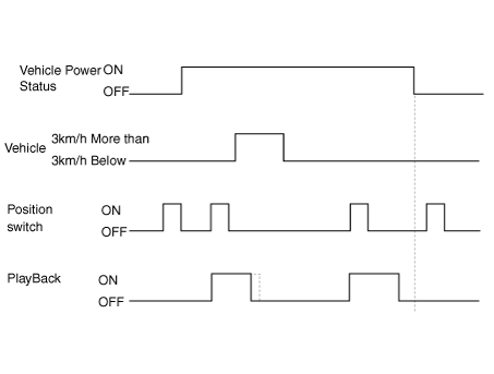
|
Decision on the Operation Priority
|
1. |
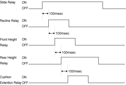
For automatic control, the motor operation shall be delayed by 100±10m
sec to prevent the overlapping of inrush circuit and in this case the
priority shall be given as follows.
Slide > Backrest adjustment >Front height adjustment >Rear height adjustment
> Cushion extension adjustment
Operation time chart
|
Operation Linked with Getting On/ Getting Off
|
1. |
Returning motion to backwards during getting off and to forwards during
getting on (applied only to slide).
|
|
2. |
It is available when the automatic SET message transmitted from the
driver seat power window switch (DDM) is ON.
|
|
3. |
Operation starts when the engine is off and driver seat door is opened.
|
|
4. |
Moving to the targeted position of ACC ON.
|
|
5. |
Conditions for prohibiting operation.
| –
|
Vehicle speed is 3km/h or more.
|
| –
|
Power seat manual control switch is operated.
|
| –
|
Reproduction command is received while getting on the vehicle.
|
| –
|
Driver settings menu (USM) is OFF.
|
|
Components and components location
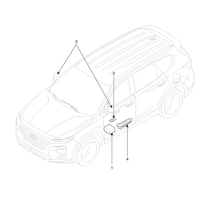
1. Seat Memory
Unit (IMS)
2. IMS control switch
|
3. Outside mirror
4. IMS mirror control (Driver power window switch)
|
Specifications
Memory Power Seat Unit
Item
|
Specification
|
Rating voltage
|
DC 12V
|
Operation voltage
|
DC 9V - 16V
|
Operation temperaure
|
-30°C to 75°C
|
parastic current
|
Max. 2mA
|
Memory Power Seat Switch
Item
|
Specification
|
Rating voltage
|
DC 5V
|
Type
|
Soft Feeling Tact type
|
category temperature range
|
-30°C to 80°C
|
Schematic diagrams
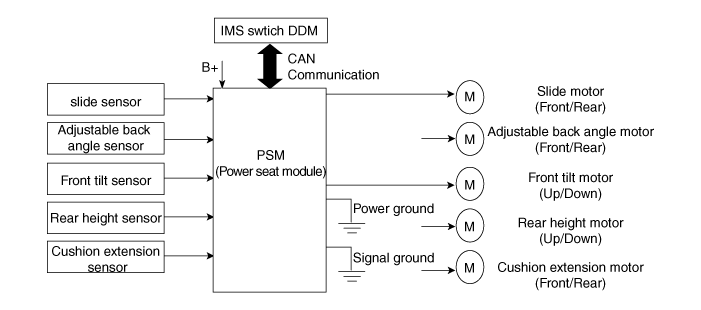
IMS (Integrated Memory System) module. Components and components location
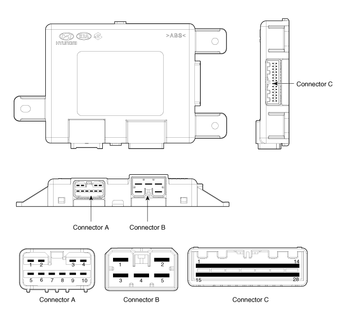
IMS input/output pin information
No
|
Connector A
|
Connector B
|
Connector C
|
1
|
Cushion extension moter (Forward)
|
B+ (Power)
|
Seat slide motor switch (Forward)
|
2
|
Seat recline motor (Forward)
|
Ground (Power)
|
Seat recline switch (Forward)
|
3
|
Seat height motor (Up)
|
B+ (Power)
|
Seat tilt switch (Up)
|
4
|
Seat slide motor(Forward)
|
-
|
Seat height switch (Up)
|
5
|
Seat Cushion extension moter (Backward)
|
Ground
|
Seat cushion extension switch (Forward)
|
6
|
Seat recline motor (Backward)
|
|
B_CAN (High)
|
7
|
Seat tilt motor (Up)
|
B_CAN (Low)
|
8
|
Seat tilt motor (Down)
|
Driver lumber support motor (Up)
|
9
|
Seat height motor (Down)
|
Driver lumber support motor (Mid)
|
10
|
Seat slide motor (Backward)
|
Seat slide sensor
|
11
|
|
Seat tilt sensor
|
12
|
Seat recline limit switch (Forward)
|
13
|
Seat position sensor power
|
14
|
IGN 1
|
15
|
Seat slide switch (Backward)
|
16
|
Seat recline switch (Backward)
|
17
|
Seat tilt switch (Down)
|
18
|
Seat height switch (Down)
|
19
|
Seat cushion extension switch (Backward)
|
20
|
Ground
|
21
|
Driver lumber support motor (Low)
|
22
|
-
|
23
|
Driver lumber support motor (Def)
|
24
|
Seat recline sensor
|
25
|
Seat height sensor
|
26
|
Seat cushion extension limit sensor
|
27
|
Seat recline limit switch (Backward)
|
28
|
Battery (+)
|
Circuit Diagram
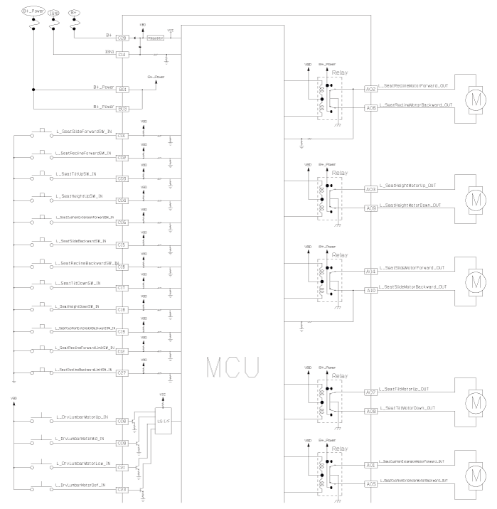
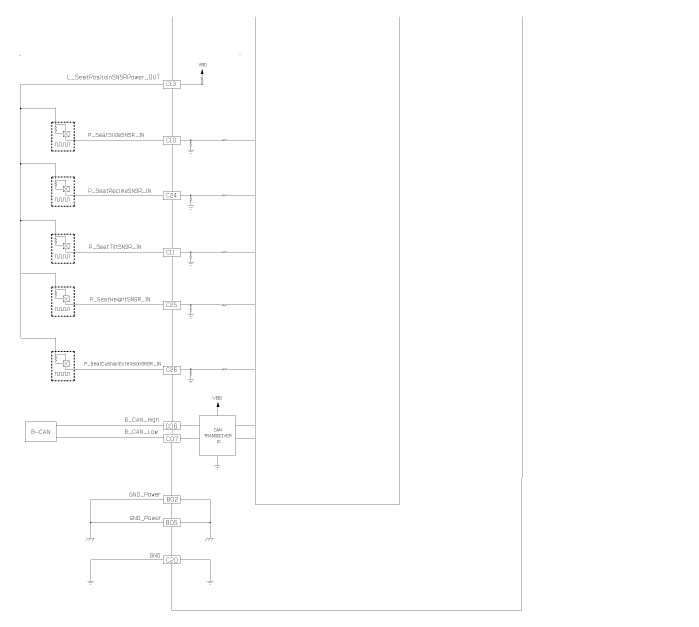
IMS (Integrated Memory System) module. Repair procedures
|
1. |
Remove the negative (-) battery terminal.
|
|
2. |
Remove the front seat assembly.
(Refer to Body - "Front Seat Assembly")
|
|
3. |
Remove the IMS module (B) after disconnecting the connector (A) and
loosening the screws (3EA).
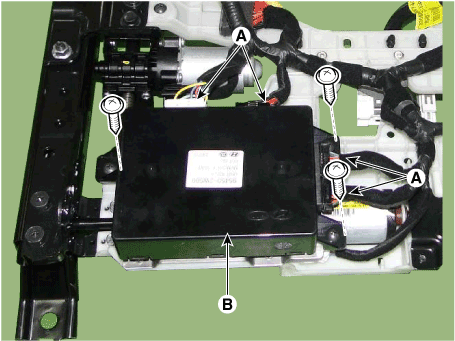
|
|
1. |
Install the IMS module after reconnecting the connector.
|
|
2. |
Install the driver seat.
|
– |
Make sure the IMS module connectors and related connectors
are plugged in properly.
|
|
– |
Check that IMS system operates normally.
|
|
|
IMS Control Switch. Components and components location
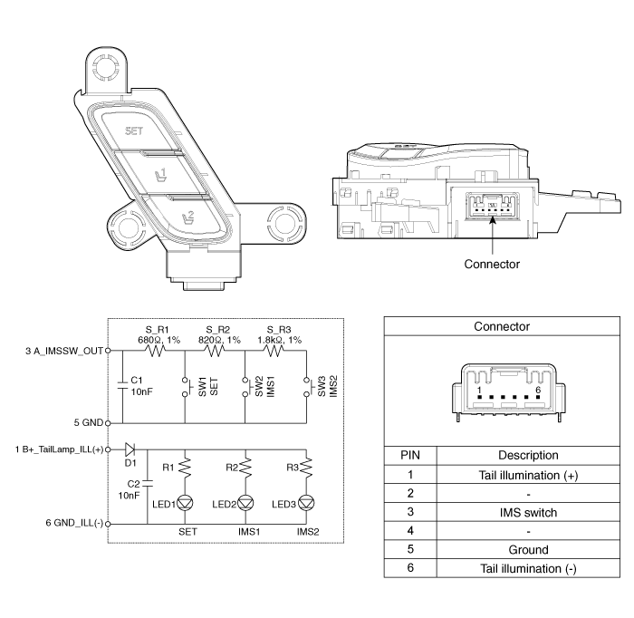
IMS Control Switch. Repair procedures
|
1. |
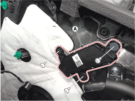
Disconnect the IMS control switch connector.
|
|
2. |
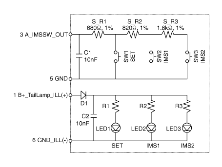
With the power IMS control switch in each position, make sure that continuity
exists between the terminals below. If continuity is not as specified,
replace the IMS control switch.
|
|
1. |
Disconnect the negative (-) battery terminal.
|
|
2. |
Remove the front door trim.
(Refer to Body - "Front Door Trim")
|
|
3. |
Disconnect the IMS switch connector and then remove the IMS switch (A).

|
| –
|
Make sure that the IMS control switch connectors and related
connectors are plugged in properly.
|
| –
|
Check the IMS control switch operates normally.
|
|
|
1. |
Connect the connectors and reassemble the IMS control switch.
|
|
2. |
Reassemble the front door trim.
|
Description and operation Description Body Control Module Controls The Followings – Wiper & Washer Control – Defroster Control – Driving Control – Tailgate Control – Window Control – Interior ...
Components and components location Component Location 1. Lumber support motor (Vertical) 2. Lumbar support motor (Horizontal) 3. Reclining motor 4. Rear height motor 5. Front height motor 6. Slide motor ...
See also:
Components and Components Location
Component Location 1. Overdrive Clutch (OD/C) 2. One way Clutch (OWC) 3. Low & Reverse Brake (LR/B) 4. Underdrive Brake (UD/B) 5. 26 Brake(26/B) 6. 35R Clutch (35R/C) 7. Damper Clutch (D/C) ...
Automatic transaxle
Depress the brake pedal and the lock release button when shifting. (If the shift lock system is not equipped, it is not necessary to depress the brake pedal. However, it is recommended to depress the ...
Underdrive Brake Control Solenoid Valve(UD/B_VFS). Specifications
Specifications Direct control VFS[UD/B] ▷ Control type : Normal high type Control Pressure kpa (kgf/cm², psi) 500.14~9.81 (5.1~0.1,72.54~1.42) Current value(mA) 50~850 Internal resistance(Ω) ...
 Hyundai Santa Fe (TM): IMS (Integrated Memory)


 Integrated Body Control Unit (IBU)
 Seat Electrical


