 Hyundai Santa Fe (TM): Seat Electrical
Components and components location
| Component Location |
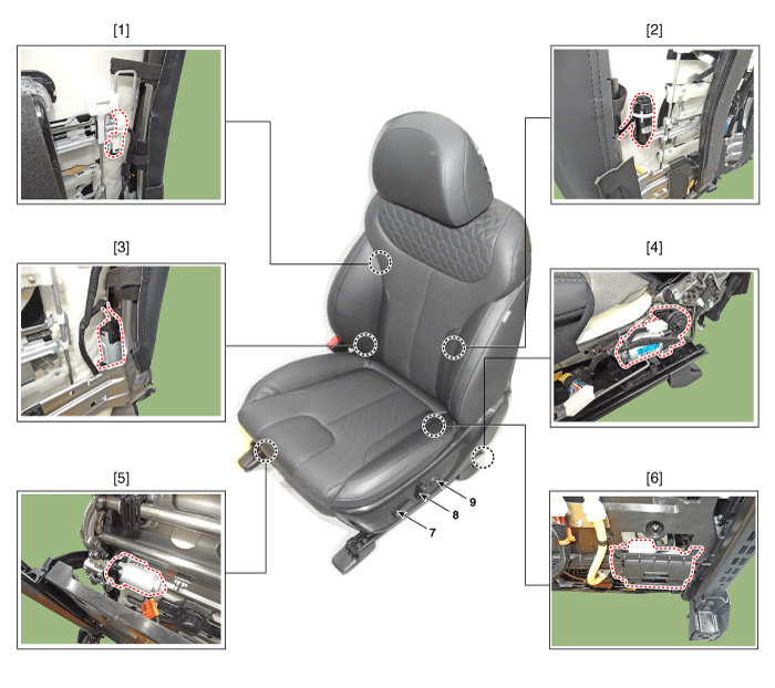
| 1. Lumber support
motor (Vertical) 2. Lumbar support motor (Horizontal) 3. Reclining motor 4. Rear height motor 5. Front height motor |
6. Slide motor 7. Power seat switch 8. Reclining switch 9. Lumbar support switch |
Inspection
| Inspection |
| 1. |
Basic inspection is performed as follows.
|
| 1. |
The body electrical system can be more quickly diagnosed for problems
by using the diagnostic tool (Refer to "DTC guide").
- Diagnosis contents may be different for each vehicle type.
|
| 1. |
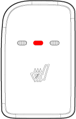
Self-diagnosis mode is entered through the operation of the seat heater
switch.
|
| 2. |
Enter the self-diagnostic mode by referring to the description below.
|
| 3. |
Check the details of the fault according to the blinking and lighting
status of the indicator after entering the self-diagnosis mode.
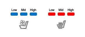
[Heater seat - when applying 3 level / 3 pin indicator output]
[Heater seat - when applying 3 level / 2 pin indicator output]
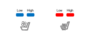
[Heater seat - when applying 2 level]
[Air ventilated seat - when applying 3 level]
[Air ventilated seat - when applying 2 level]
|
|||||||||||||||||||||||||||||||||||||||||||||||||||||||||||||||||||||||||||||||||||||||||||||||||||||||||||||||||||||||||||||||||||||||||||||||||||||||||||||||||||||||||||||||||||||||||||||||||||||||||||||||||||||||||||||||||||||||||||||||||||||||||||||||||||||||
| 4. |
If IGN is OFF, the fault diagnosis mode of the heater & air ventilated
seat is terminated.
|
Power Seat Motor. Repair procedures
| Inspection |
| 1. |
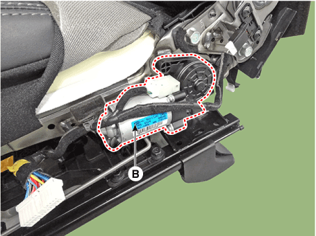
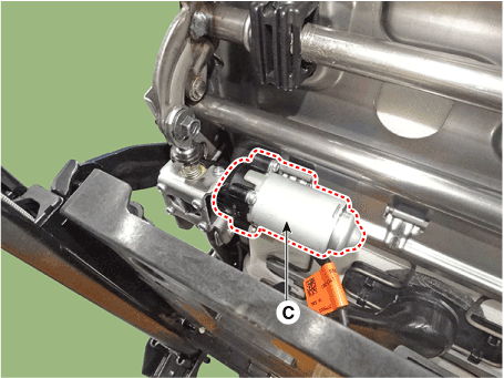
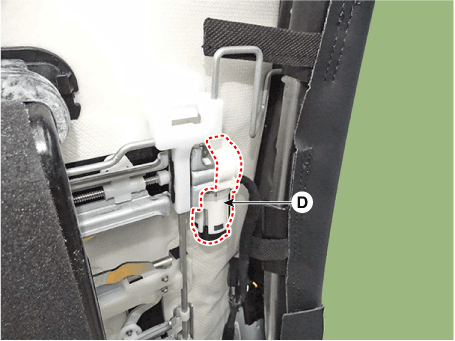
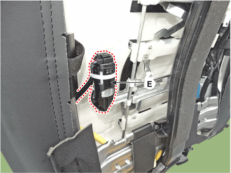
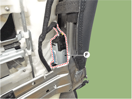
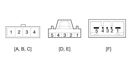
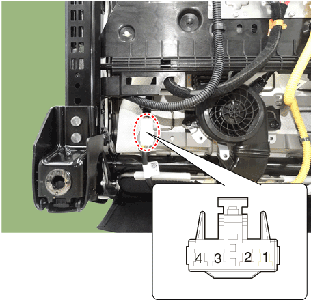
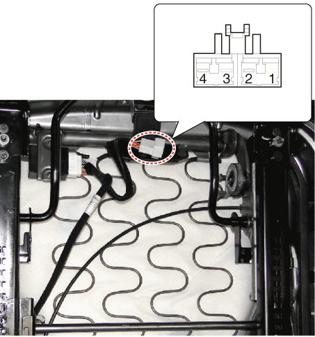
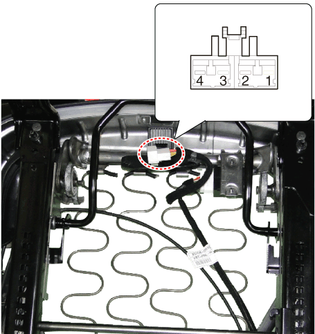
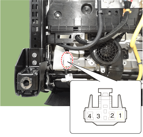
Disconnect the connectors for each motor.
(Refer to Body - "Front Seat Assembly")
B : Rear height motor
C : Front height motor
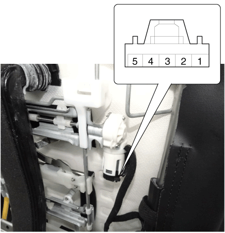
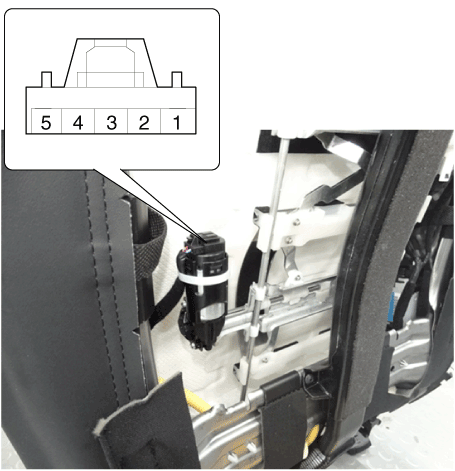
D : Lumbar support motor (Horizontal)
E : Lumbar supprot motor (Vertical)
F : Recline motor
|
| 2. |
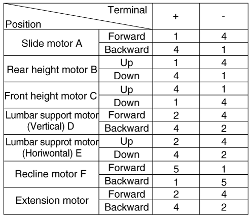
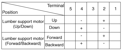
With the battery connected directly to the motor terminals, check if
the motors run smoothly.
|
| 3. |
Reverse the connections and check that the motor turns in reverse.
|
| 4. |
If there is an abnormality, replace the motors.
|
| 1. |
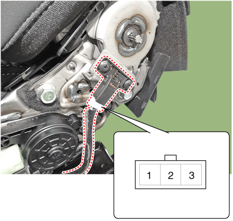
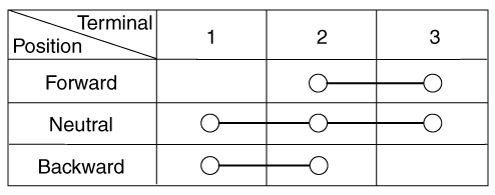
Disconnect the limit switch and operate the limit switch.
|
| 2. |
|
| 3. |
Make sure that the seat operation is normal in the reverse after the
maximum operation.
|
| 4. |
If there is an abnormality, replace the limit switch.
|
Power Seat Control Switch. Schematic diagrams
| Circuit Diagram |
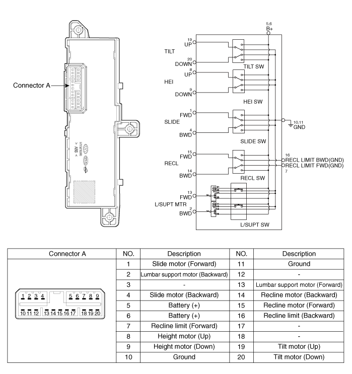
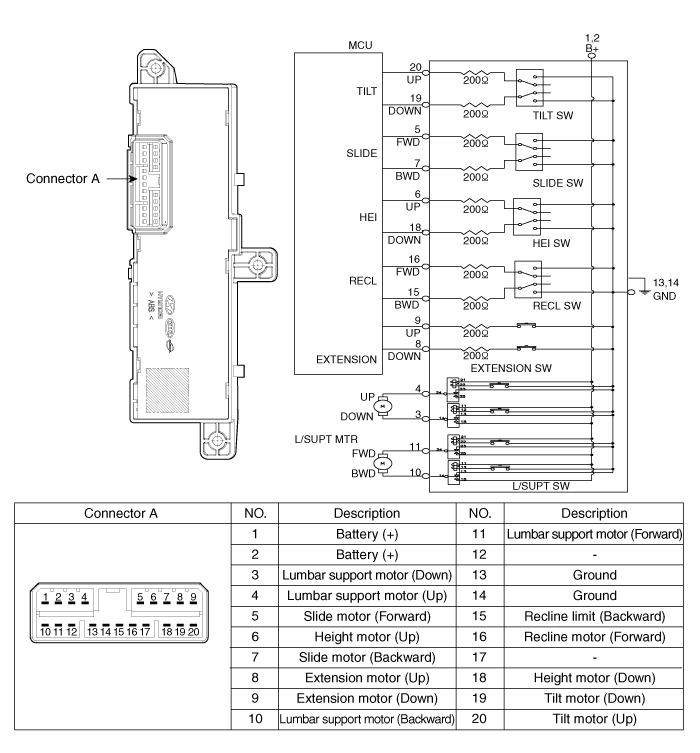
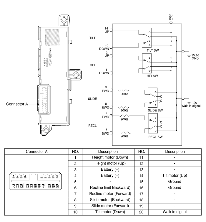
Power Seat Control Switch. Repair procedures
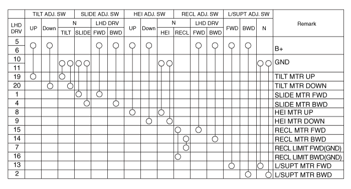
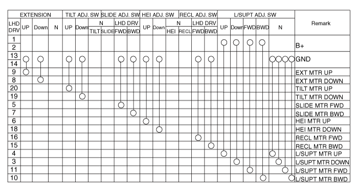
| Inspection |
| 1. |
With the power seat switch in each position, make sure that continuity
exists between the terminals below. If continuity is not as specified,
replace the power seat switch.
|
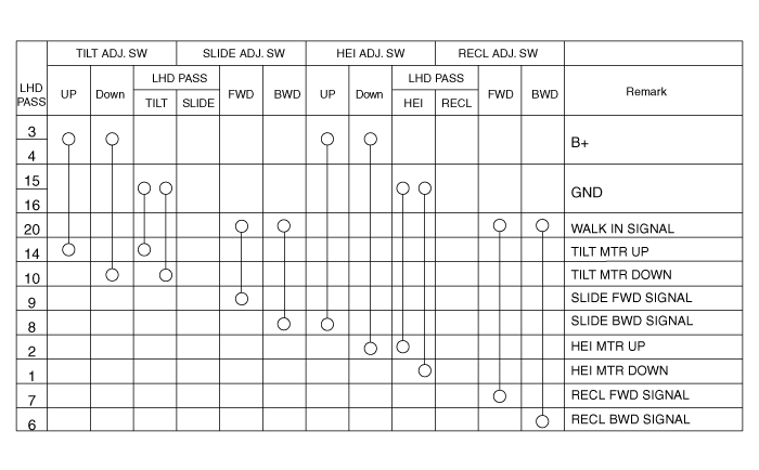
| Removal |
| 1. |
Disconnect the negative (-) battery terminal.
|
| 2. |
Remove the front seat shield outer cover.
(Refer to Body - "Front Seat Shield Outer Cover")
|
| 3. |
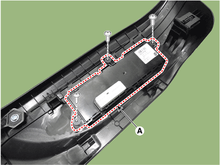
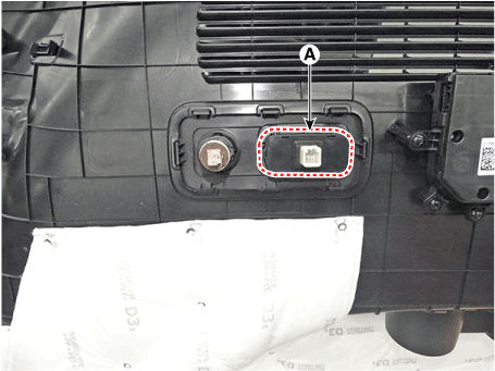
Remove the power seat control switch (A) after loosening the screws
(2EA).
|
| Installation |
| 1. |
Install the power seat control switch after connecting the connector.
|
| 2. |
Install the front seat shield outer cover.
|
| 3. |
Connect the negative (+) battery terminal.
|
Lumber Support System. Repair procedures
| Removal |
| 1. |
Disconnect the negative (-) battery terminal.
|
| 2. |
Remove the front seat back cover.
(Refer to Body - "Front Seat Back Cover")
|
| 3. |
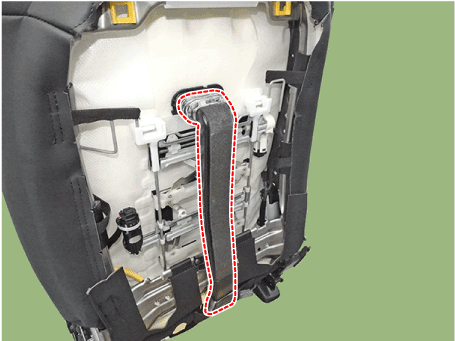
Remove the air duct.
|
| 4. |
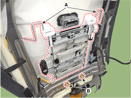
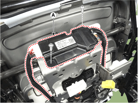
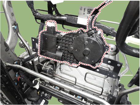
Disconnect the lumber support motor connector (D)&(E).
|
| 5. |
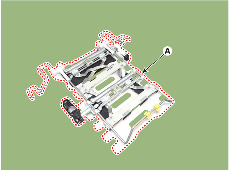
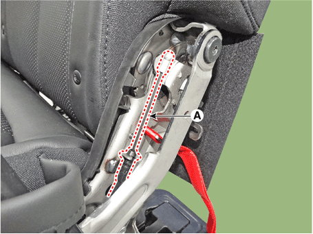
Remove the lumber support assembly after removing the rod (A) & mounting
fasner (B).
|
| Installation |
| 1. |
Install the lumber support assembly.
|
| 2. |
Install the seat back cover.
|
| 3. |
Install the front seat assembly.
|
| Inspection |
| 1. |
Disconnect the connectors for motor.
|
| 2. |
When the battery power is supplied to the motor connector, check the
motor for smooth operation.
|
| 3. |
Reverse the connections and check that the motor turns in reverse.
|
| 4. |
If the motor runs abnormally, replace it.
|
Seat Heater Switch. Components and components location
| Components |
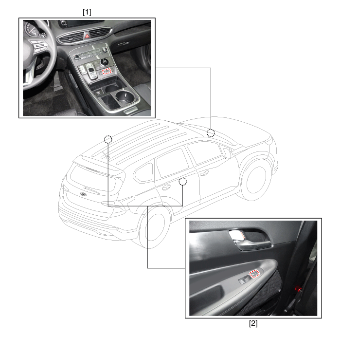
| 1. Front seat
heater switch |
2. Rear seat
heater switch |
Seat Heater Switch. Schematic diagrams
| Circuit Diagram |
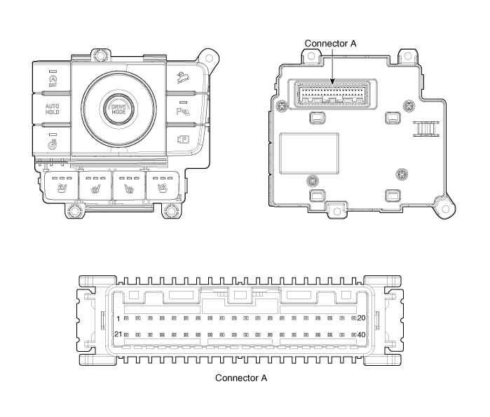
|
Pin |
Description |
Pin |
Description |
|
1 |
C-CAN (High) |
21 |
ILL (+) |
|
2 |
C-CAN (Low) |
22 |
- |
|
3 |
- |
23 |
ILL (-) |
|
4 |
- |
24 |
Right seat heater signal |
|
5 |
- |
25 |
Right seat heater IND MIN |
|
6 |
IGN |
26 |
Right seat heater IND MID |
|
7 |
- |
27 |
Right seat heater IND MAX |
|
8 |
Auto hold signal |
28 |
Right ventilation seat signal |
|
9 |
PDW signal |
29 |
Right ventilation seat IND MIN |
|
10 |
Steering wheel heater signal |
30 |
Right ventilation seat IND MID |
|
11 |
SVM signal |
31 |
Right ventilation seat IND MAX |
|
12 |
ISG signal |
32 |
Left seat heater signal |
|
13 |
DBC signal |
33 |
Left seat heater IND MIN |
|
14 |
- |
34 |
Left seat heater IND MID |
|
15 |
Steering wheel heater IND |
35 |
Left seat heater IND MAX |
|
16 |
ISG IND |
36 |
Left ventilation seat signal |
|
17 |
PDW IND |
37 |
Left ventilation seat IND MIN |
|
18 |
DETENT signal |
38 |
Left ventilation seat IND MID |
|
19 |
- |
39 |
Left ventilation seat IND MAX |
|
20 |
Ground |
40 |
- |
Seat Heater Switch. Repair procedures
| Removal |
| 1. |
Disconnect the negative (-) battery terminal.
|
| 2. |
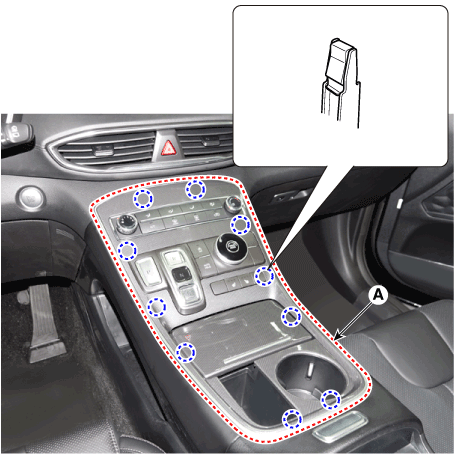
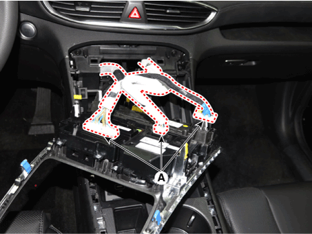
Remove the console upper cover (A).
|
| 3. |
Press the lock pin, separate the connectors (A).
|
| 4. |
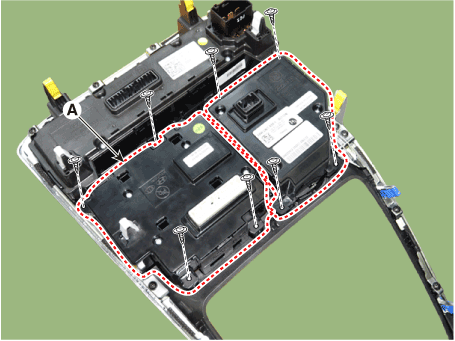
Remove the seat heater switch (A) and SBW switch assembly after loosening
mounting screws.
|
| Installation |
| 1. |
Install the front seat heater switch.
|
| 2. |
Connect the negative (-) battery terminal.
|
Seat Heater (Non-Air Ventilation). Components and components location
| Components |
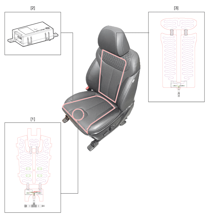
| 1. Seat cushion
heater 2. Seat heater unit (Passenger only) |
3. Seat back
heater |
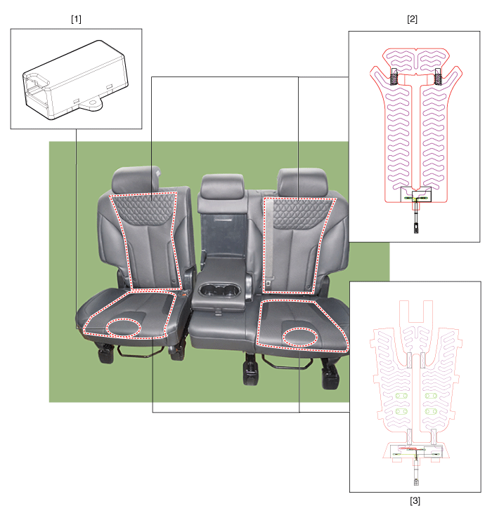
| 1. Seat heater
unit 2. Seat back heater |
3. Seat cushion
heater |
Seat Heater (Non-Air Ventilation). Schematic diagrams
| Components |
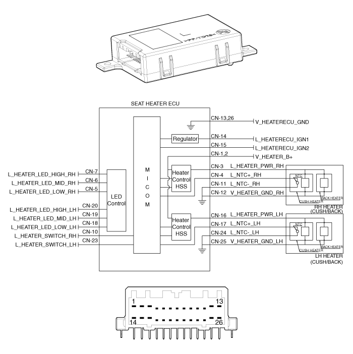
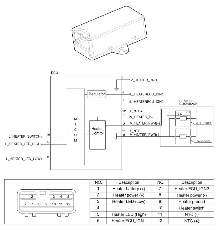
Seat Heater (Non-Air Ventilation). Repair procedures
| Inspection |
| 1. |
Check for continuity and measure the resistance between terminals.
|
| 2. |
Operate the seat heater after connecting the connector, and then check
the thermostat by measuring the temperature of seat surface.
|
| 1. |
Check for continuity and measure the resistance between terminals.
[RH]
[LH]
|
|||||||||||||||||||||
| 2. |
Operate the seat heater after connecting the connector, and then check
the thermostat by measuring the temperature of seat surface.
|
|||||||||
| 1. |
Enter the diagnostic mode referring to below description.
|
| 2. |
After entering the diagnosis mode, you can check what failed by checking
the blinking LED.
|
| 3. |
The table below indicates the failure based on priority, upper item
means higher priority.
|
| 4. |
If more than one failure is detected, higher priority failure is displayed
through the LED flashing pattern.
|
| 5. |
Lower priority failure will be displays if higher priority failure is
reset.
[Heater Switch]
[Driver/Passenger]
[Second line seat heater]
|
| 6. |
If you press the seat heater button for more than five seconds, the
LED for malfunctioning memory will blink four times and the recorded
memory will be deleted.
|
| 7. |
Pressing the IGN OFF button will end the diagnosis mode for the seat.
|
| 8. |
You can check whether the heating seat system works properly after turning
the IGN ON. If you want to check the error code, you can refer to the
procedure of 2 above.
|
Seat Heater (Air Ventilation). Components and components location
| Components |
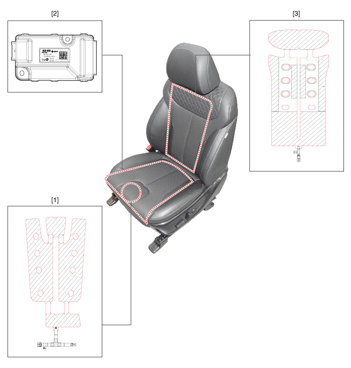
| 1. Seat cushion
heater 2. Seat heater unit (Passenger only) |
3. Seat back
heater |
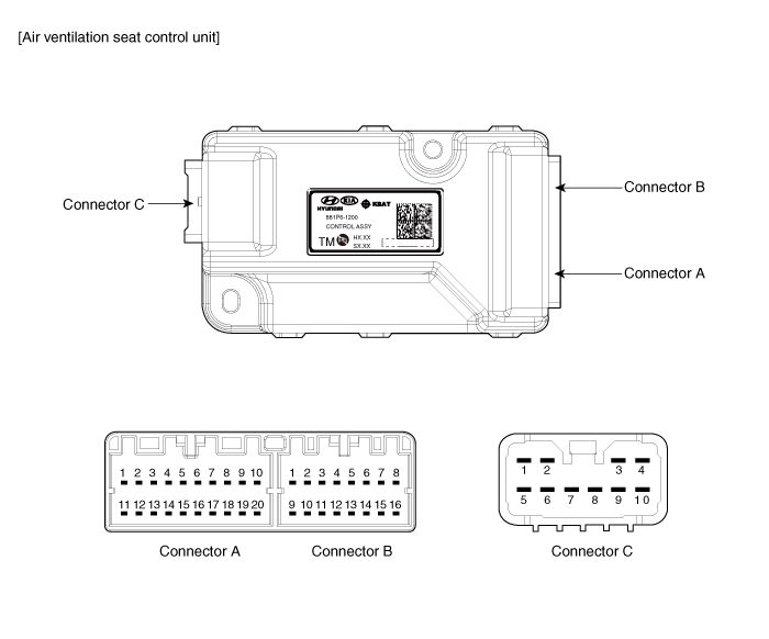
|
No. |
Connector A |
Connector B |
Connector C |
|
1 |
Vent heater ECU _ IGN1 |
Driver vent switch LED (Low) |
Vent / heater power |
|
2 |
Driver blower power |
Driver vent switch LED (Mid) |
Driver heater power |
|
3 |
Driver blower speed |
Driver vent switch LED (High) |
Driver heater ground |
|
4 |
Driver RPM input |
Driver NTC (+) |
Driver / Assist, Vent / Heater ground |
|
5 |
Driver heater switch |
- |
vent / heater power |
|
6 |
Driver vent switch |
Illumination (-) |
- |
|
7 |
Illumination (+) |
Driver NTC (-) |
Assist heater power |
|
8 |
Driver heater LED (Low) |
Driver blower ground |
- |
|
9 |
Driver heater LED (Mid) |
Driver vent led (Low) |
Assist heater ground |
|
10 |
Driver heater LED (High) |
Driver vent led (Mid) |
Driver / Assist, Vent / Heater ground |
|
11 |
Vent seat unit IGN 2 |
Driver vent led (High) |
|
|
12 |
Assist blower power |
Assist NTC (+) |
|
|
13 |
Assist blower speed |
FATC PWM |
|
|
14 |
Assist blower RPM input |
- |
|
|
15 |
Assist heater switch |
Assist NTC (-) |
|
|
16 |
Assist vent switch |
Assist blower ground |
|
|
17 |
Detent |
|
|
|
18 |
Assist heater LED (Low) |
||
|
19 |
Assist heater LED (Mid) |
||
|
20 |
Assist heater LED (High) |
Seat Heater (Air Ventilation). Schematic diagrams
| Circuit Diagram |
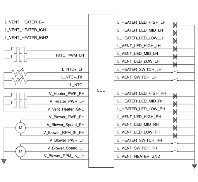
Seat Heater (Air Ventilation). Repair procedures
| Inspection |
| 1. |
Check for continuity and measure the resistance between terminals.
|
| 2. |
Operate the seat heater after connecting the connector, and then check
the thermostat by measuring the temperature of seat surface.
|
Air Ventilation Seat. Components and components location
| Component Location |
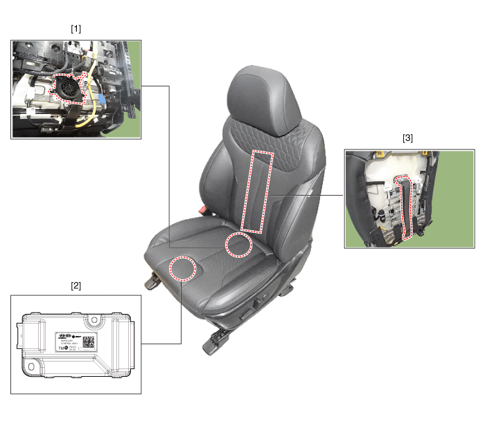
| 1. Air ventilation
seat blower 2. Air ventilation seat control unit (Passenger only) |
3. Air ventilation
seat duct |
Air Ventilation Seat. Schematic diagrams
| Circuit Diagram |

|
No. |
Connector A |
Connector B |
Connector C |
|
1 |
Vent heater ECU _ IGN1 |
Driver vent switch LED (Low) |
Vent / heater power |
|
2 |
Driver blower power |
Driver vent switch LED (Mid) |
Driver heater power |
|
3 |
Driver blower speed |
Driver vent switch LED (High) |
Driver heater ground |
|
4 |
Driver RPM input |
Driver NTC (+) |
Driver / Assist, Vent / Heater ground |
|
5 |
Driver heater switch |
- |
vent / heater power |
|
6 |
Driver vent switch |
Illumination (-) |
- |
|
7 |
Illumination (+) |
Driver NTC (-) |
Assist heater power |
|
8 |
Driver heater LED (Low) |
Driver blower ground |
- |
|
9 |
Driver heater LED (Mid) |
Driver vent led (Low) |
Assist heater ground |
|
10 |
Driver heater LED (High) |
Driver vent led (Mid) |
Driver / Assist, Vent / Heater ground |
|
11 |
Vent seat unit IGN 2 |
Driver vent led (High) |
|
|
12 |
Assist blower power |
Assist NTC (+) |
|
|
13 |
Assist blower speed |
FATC PWM |
|
|
14 |
Assist blower RPM input |
- |
|
|
15 |
Assist heater switch |
Assist NTC (-) |
|
|
16 |
Assist vent switch |
Assist blower ground |
|
|
17 |
Detent |
|
|
|
18 |
Assist heater LED (Low) |
||
|
19 |
Assist heater LED (Mid) |
||
|
20 |
Assist heater LED (High) |
Air Ventilation Seat. Repair procedures
| Removal |
| 1. |
Remove the front seat assembly.
(Refer to Body - "Front Seat Assembly")
|
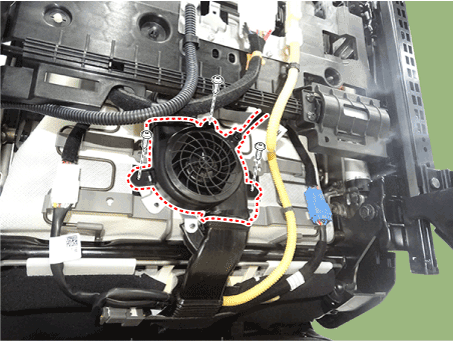
| 2. |
Remove the cushion blower(A) after loosening the screws(3EA) and disconnecting
the connector.
|
| 1. |
Remove the front seat assembly.
(Refer to Body - "Front Seat Assembly")
|
| 2. |
Remove the air duct (A) after loosening the screws and disconnecting
the connector.
|
| 1. |
Remove the front seat assembly.
(Refer to Body - "Front Seat Assembly")
|
| 2. |
Remove the air ventilation unit(A) after loosening the screws(2EA) and
disconnecting the connector.
|
| Installation |
| 1. |
Install the cushion blower.
|
| 2. |
Install the front seat assembly.
|
| 1. |
Install the air duct.
|
| 2. |
Install the front seat assembly.
|
| 1. |
Install the air ventilation unit.
|
| 2. |
Install the front seat assembly.
|
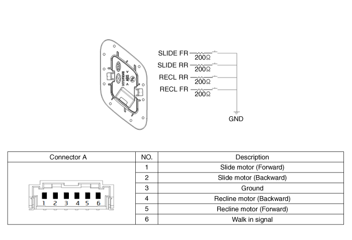
Walk-in Switch. Components and components location
| Component Location |
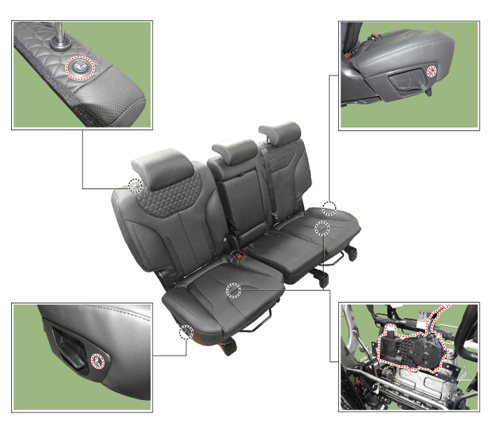
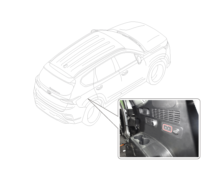
Walk-in Switch. Schematic diagrams
| Circuit Diagram |
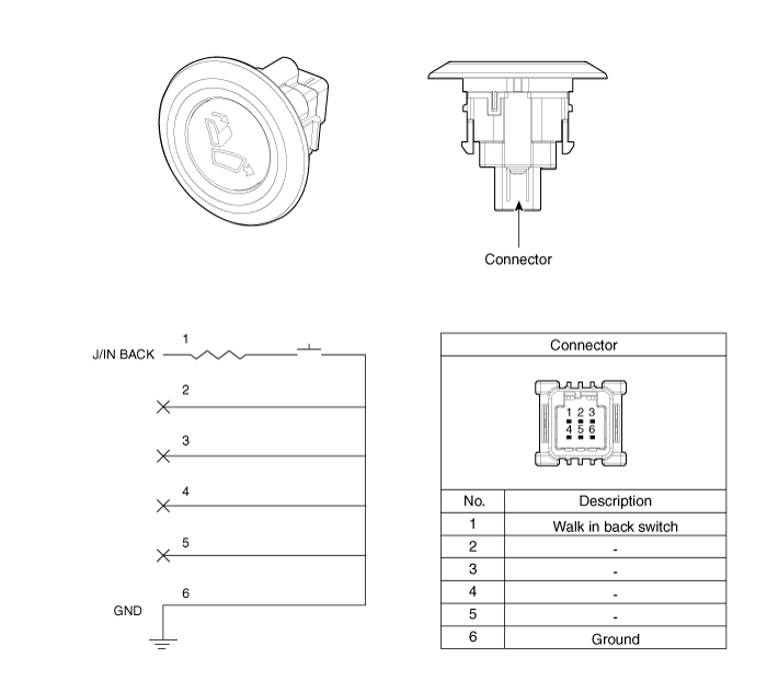
Walk-in Switch. Repair procedures
| Removal |
| 1. |
Remove the rear seat.
(Body - "Rear Seat Assembly")
|
| 2. |
Disconnect the walk in actuator connector and then remove the actuator.
|
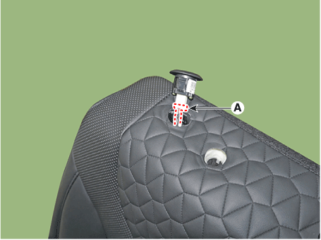
| 3. |
Remove the cable (A) and then separate the walk in actuator.
|
| 1. |
Remove the rear seat walk in switch (A).
|
| 2. |
Remove the walk in switch by using a flat-head screwdriver and then
disconnect the walk in switch connector (A).
|
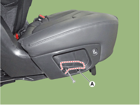
| 1. |
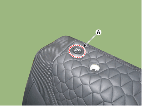
Loosen the screw and then remove the rear seat recliner knob (A).
|
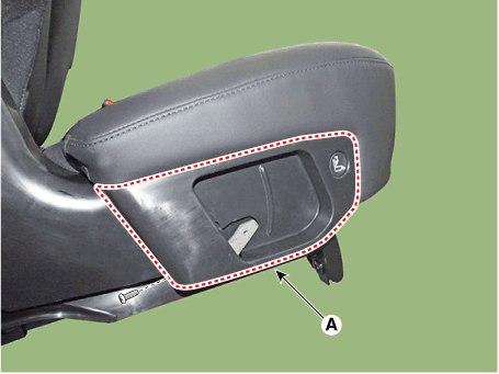
| 2. |
Loosen the screw and then remove the rear seat recliner cover (A).
|
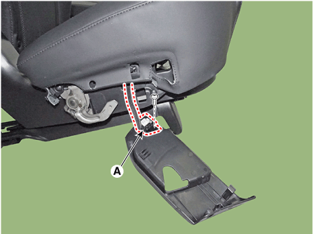
| 3. |
Remove the walk in swtich (A) after loosening the connector.
|
| 1. |
Remove the luggage side trim.
(Refer to Body - "Luggage Side Trim")
|
| 2. |
Remove the luggage remote folding switch (A).
|
 IMS (Integrated Memory)
Description and operation Description The optimal seat position set by the driver is memorized into the power seat unit by using IMS switch. In case of the position change, the seat can restore its preset ...
 Fuel Filler Door
Components and components location Component Location 1. Fuel filler door release actuator Fuel Filler Door Release Actuator. Repair procedures Removal 1. Remove the left luggage side trim. (Refer to Body ...
See also:
Jump starting
Jump starting can be dangerous if done incorrectly. Therefore, to avoid harm to yourself or damage to your vehicle or battery, follow the jump starting procedures. If in doubt, we strongly recommend that ...
Engine Oil Pressure Warning Light
This warning light illuminates: Once you set the ignition switch or Engine Start/Stop Button to the ON position. - It remains on until the engine is started. When the engine oil pressure is low. If the ...
Instrument panel overview
1. Lighting control lever 2. Audio remote control buttons 3. Bluetooth hands-free buttons 4. Cruise control button 5. Flex steer control button 6. LCD display control buttons 7. Horn 8. Driver’s front ...


