 Hyundai Santa Fe (TM): Indicators And Gauges
Troubleshooting
| Troubleshooting |
|
Symptom |
Possible cause |
Remedy |
|
Speedometer does not operate |
Cluster fuse (10A) blown |
Check for short and replace fuse |
|
Speedometer faulty |
Check speedometer |
|
|
CAN line faulty |
Check the EMS |
|
|
Wiring or ground faulty |
Repair if necessary |
|
|
Tachometer does not operate |
Cluster fuse (10A) blown |
Check for short and replace fuse |
|
Tachometer faulty |
Check tachometer |
|
|
CAN line faulty |
Check the EMS |
|
|
Wiring or ground faulty |
Repair if necessary |
|
|
Fuel gauge does not operate |
Cluster fuse (10A) blown |
Check for short and replace fuse |
|
Fuel gauge faulty |
Check gauge |
|
|
Fuel sender faulty |
Check fuel sender |
|
|
Wiring or ground faulty |
Repair if necessary |
|
|
Low fuel warning lamp does not light up |
Cluster fuse (10A) blown |
Check for short and replace fuse |
|
Bulb burned out |
Replace bulb |
|
|
Fuel sender faulty |
Check fuel sender |
|
|
Wiring or ground faulty |
Repair if necessary |
|
|
Water temperature gauge does not operate |
Cluster fuse (10A) blown |
Check for short and replace fuse |
|
Water temperature gauge faulty |
Check gauge |
|
|
Water temperature sender faulty |
Check sender |
|
|
CAN line faulty |
Check the EMS |
|
|
Wiring or ground faulty |
Repair if necessary |
|
|
Oil pressure warning lamp does not light up |
Cluster fuse (10A) blown |
Check for short and replace fuse |
|
Bulb burned out |
Replace bulb |
|
|
Oil pressure switch faulty |
Check switch |
|
|
Wiring or ground faulty |
Repair if necessary |
|
|
Parking brake warning lamp does not light up |
Cluster fuse (10A) blown |
Check for short and replace fuse |
|
Bulb burned out |
Replace bulb |
|
|
Brake fluid level warning switch faulty |
Check switch |
|
|
Parking brake switch faulty |
Check switch |
|
|
Wiring or ground faulty |
Repair if necessary |
|
|
Open door warning lamp and tailgate warning lamp do not light up |
Memory fuse (15A) blown |
Check for short and replace fuse |
|
Bulb burned out |
Replace bulb |
|
|
Door switch faulty |
Check switch |
|
|
Wiring or ground faulty |
Repair if necessary |
|
|
Seat belt warning lamp does not light up |
Cluster fuse (10A) blown |
Check for short and replace fuse |
|
Bulb burned out |
Replace bulb |
|
|
Seat belt switch faulty |
Check switch |
|
|
Wiring or ground faulty |
Repair if necessary |
|
|
Speedometer and odometer does not operate |
CAN line faulty |
Check the ABS ECU |
|
Wheel speed sensor faulty |
Check the wheel speed sensor |
Instrument Cluster. Description and operation
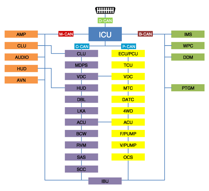
| Description |
|
Abbreviation |
Explanation |
|
IBU |
Interated Body Control Unit |
|
DDM |
Driver Door Module |
|
PTGM |
Power Tail Gate Module |
|
ICU |
Interated Control Unit |
|
PCU |
Powertrain Control Unit |
|
ECU |
Engine Control Unit |
|
CLU |
Cluster |
|
MDPS |
Moter Driven Power Steering |
|
SVM |
Sorround View Monitor |
|
ACU |
Airbag Control Unit |
|
VDC |
Vehicle Dynamic Control |
|
SCC |
Smart Cruise Control |
|
DBL |
Dynamic banding Light |
|
LKA |
Lane Keeping Assist |
|
BCW |
Blind-Spot Collision Warning |
|
RVM |
Rear View Monitor |
|
SAS |
Steering Angle Sensor |
|
HUD |
Head up Display |
|
TCU |
Transmission Control Unit |
|
MTC |
Temp Control |
|
DATC |
Dual Automatic Temp Control |
|
4WD |
Four Wheel Drive |
|
F/PUMP |
Fuel Pump Control Module |
|
V/PUMP |
Vacuum Pump |
|
OCS |
Occupant Classification System |
|
WPC |
Wireless Power Chager |
|
IMS |
Integrated Memory System |
|
AMP |
Amplifier |
|
AVN |
Head Unit (Audio / AVN) |
|
HUD |
Head Up Display |
Instrument Cluster. Components and components location
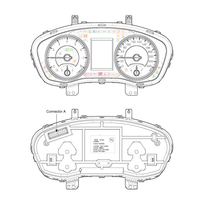
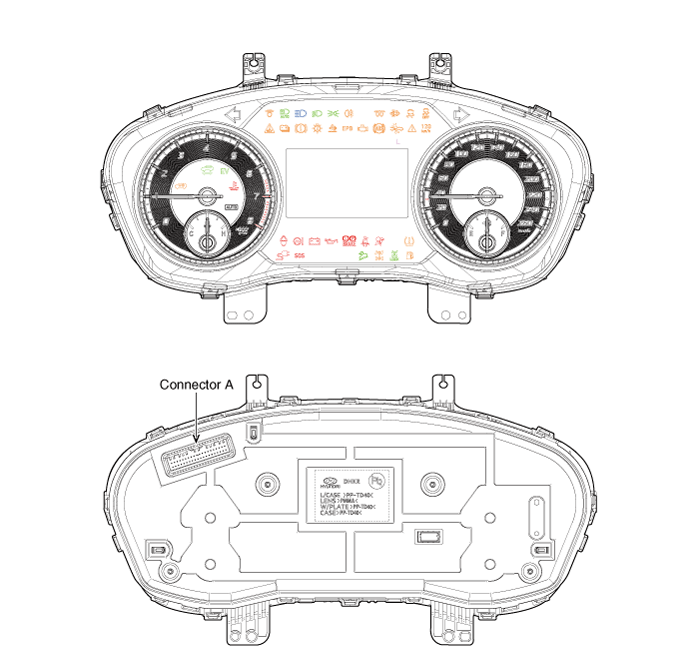
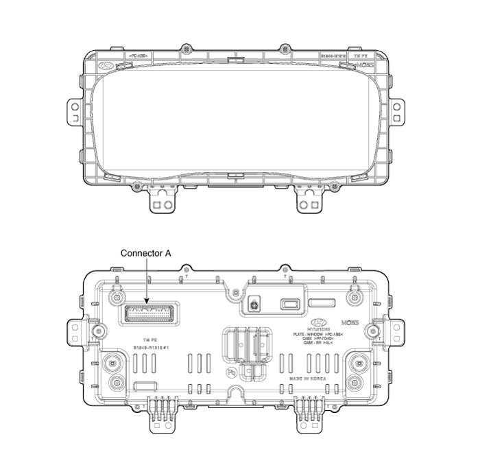
| Components |

|
No. |
Connector A |
No. |
Connector |
|
1 |
Ground |
21 |
Trip switch (-) |
|
2 |
Illumination (-) |
22 |
Trip switch 1 (+) |
|
3 |
Rheostat switch (Down)_Input |
23 |
Trip switch 2 (+) |
|
4 |
Rheostat switch (Up)_Input |
24 |
Active ECO_input switch/ R switch(M/T)_input |
|
5 |
Dentent |
25 |
Driver mode switch/ N switch(M/T)_input |
|
6 |
P |
26 |
Speaker1 (+)_Output |
|
7 |
R |
27 |
Speaker1 (-)_Output |
|
8 |
N |
28 |
Low washer level_Input |
|
9 |
D |
29 |
M-CAN (Low) |
|
10 |
S |
30 |
M-CAN (High) |
|
11 |
Immobilizer_Input |
31 |
Engine run state_Output |
|
12 |
Vehicle speed_Output |
32 |
C-CAN (High) |
|
13 |
AlTL_Input |
33 |
C-CAN(Low) |
|
14 |
Fuel sender (+)_Input |
34 |
Outside temperature_Input |
|
15 |
Vehicle speed_Input |
35 |
- |
|
16 |
Fuel sender (-)_Input |
36 |
Heated steering wheel indicator_Input |
|
17 |
Water separate_Input |
37 |
Ground |
|
18 |
Airbag (+)_Input |
38 |
IGN 3 |
|
19 |
Oilpressure switch_Input |
39 |
IGN 1 |
|
20 |
Taillamp_Input |
40 |
Battery (+) |
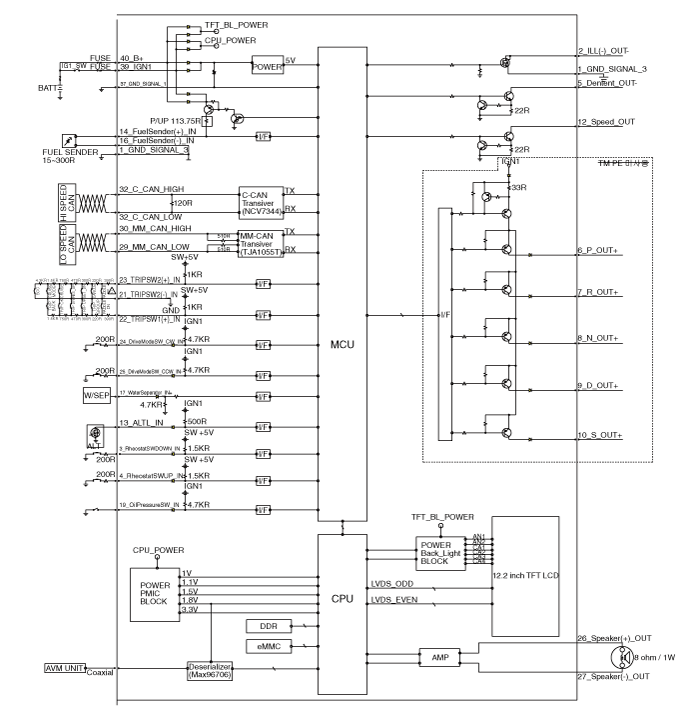
Instrument Cluster. Schematic diagrams
| Circuit Diagram |
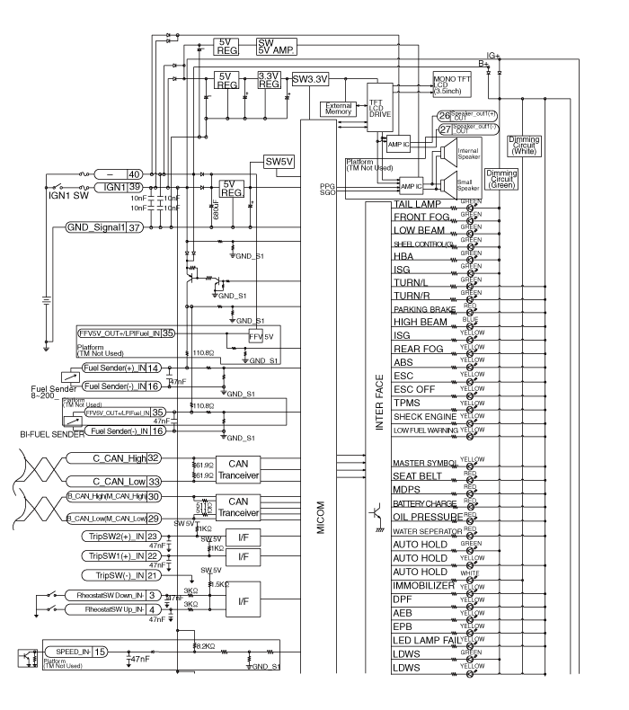
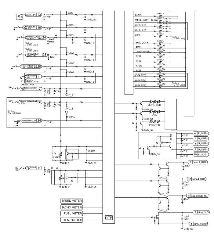
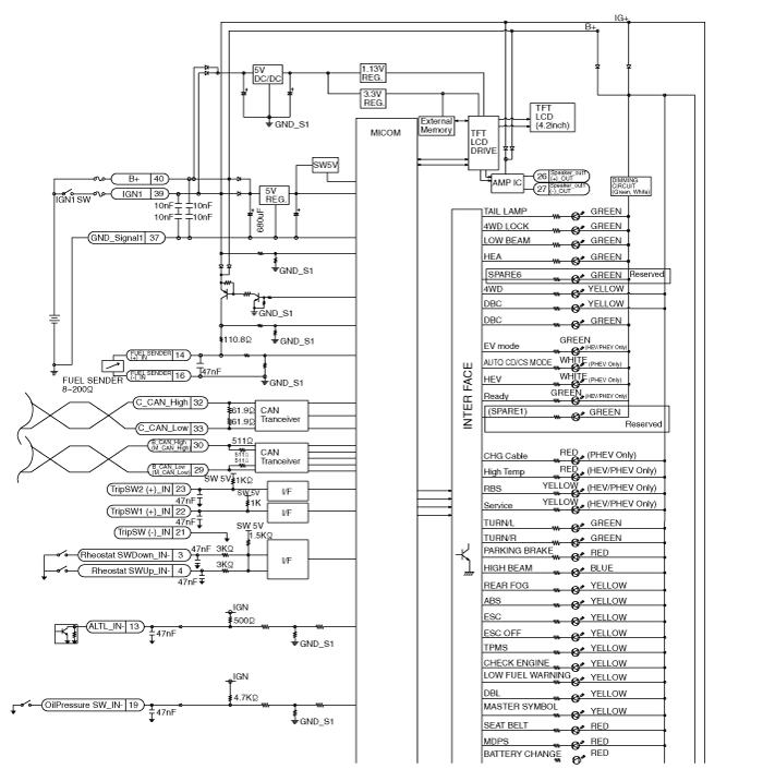
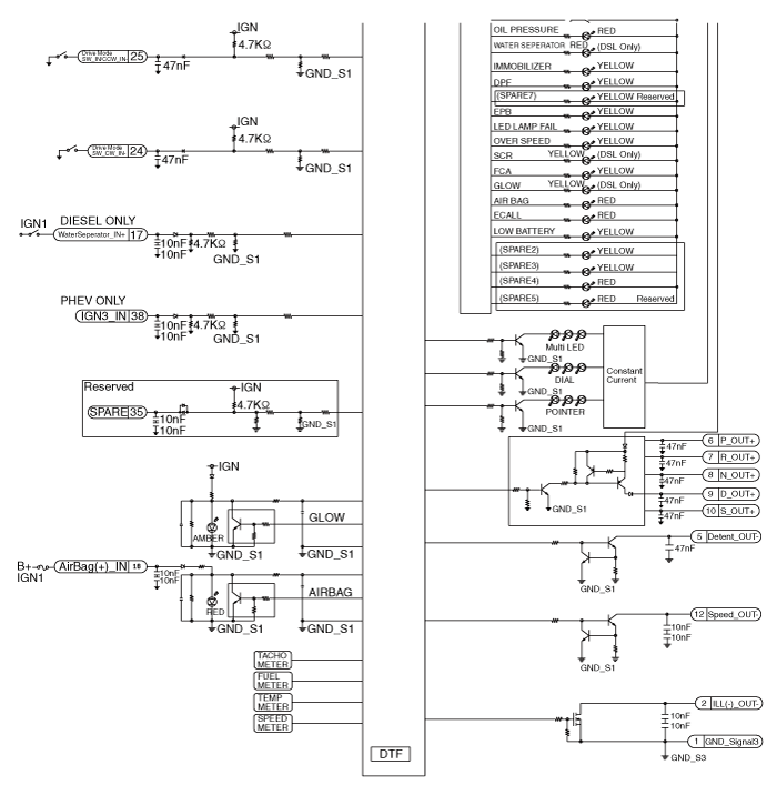
Instrument Cluster. Repair procedures
| Removal |
| 1. |
Disconnect the negative (-) battery terminal.
|
| 2. |
Remove the cluster fascia panel (A).
(Refer to Body - "Cluster Fascia Panel")
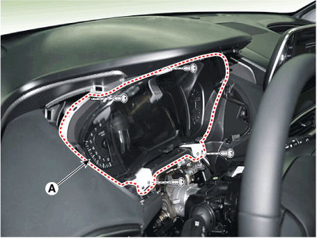
|
| 3. |
Remove the cluster (A) from the housing after removing 2 screws.
|
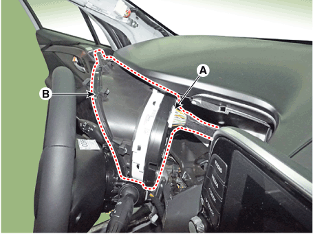
| 4. |
Disconnect the cluster connecter (A) and then remove the cluster (B).
|
| Installation |
| 1. |
Connect the cluster connector.
|
| 2. |
Install the cluster assembly.
|
| 3. |
Install the cluster facia panel.
|
| 4. |
Connect the negative (-) battery terminal.
|
| Inspection |
| 1. |
Check point (Warning indicator)
|
| 2. |
Check point (Gauge)
|
| 1. |
In the body electrical system, failure can be quickly diagnosed by using
the vehicle diagnostic system.
The diagnostic system provides the following information.
|
| 2. |
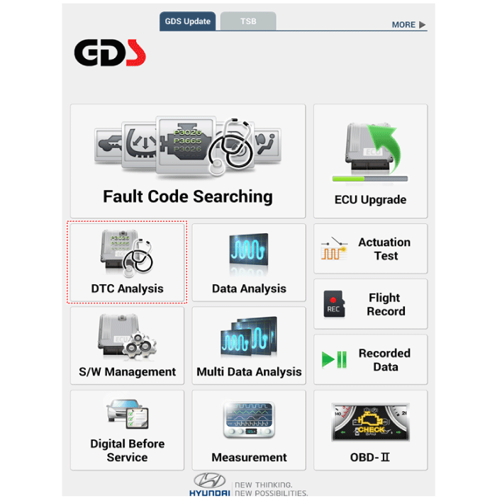
If diagnose the vehicle by diagnostic tool, select "DTC Analysis" and
"Vehicle".
|
| 3. |
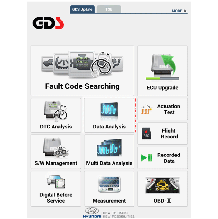
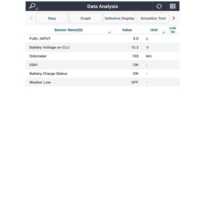
If check current status, select the "Data Analysis" and "Car model".
|
| 4. |
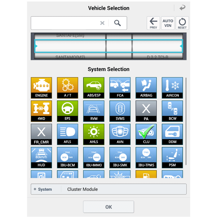
Select the 'CLU' to search the current state of the input/output data.
|
| 1. |
Connect the cable of diagnostic tool to the data link connector in driver
side crash pad lower panel.
|
| 2. |
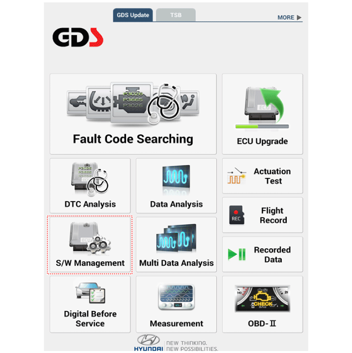
Select the 'S/W Management' and 'Car model'.
|
| 3. |
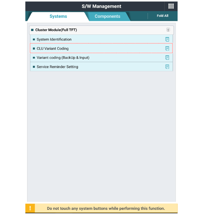
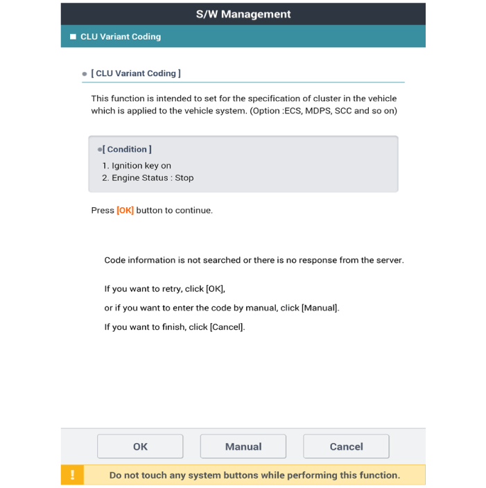
Select the 'Cluster Module' and 'CLU Variant Coding'.
|
|
| 1. |
Back up the variable coding value before replacing the cluster.
|
| 2. |
Connect the cable of diagnostic tool to the data link connector in driver
side crash pad lower panel.
|
| 3. |
Select the 'S/W Management' and 'Car model'.
|
| 4. |
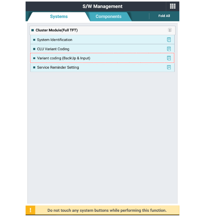
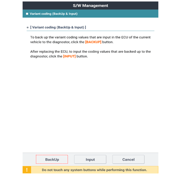
Select the 'Variant coding (Backup & Input).
|
| 5. |
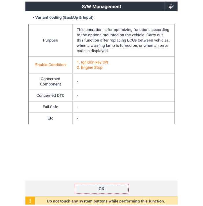
After checking purpose and enable condition, press the ‘OK’ button.
|
| 6. |
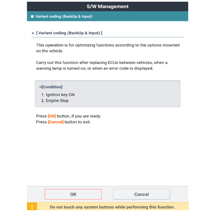
Press the ‘OK’ button.
|
| 7. |
Select ‘BackUP’ to back up the variable coding value before replacing
the cluster.
|
| 8. |
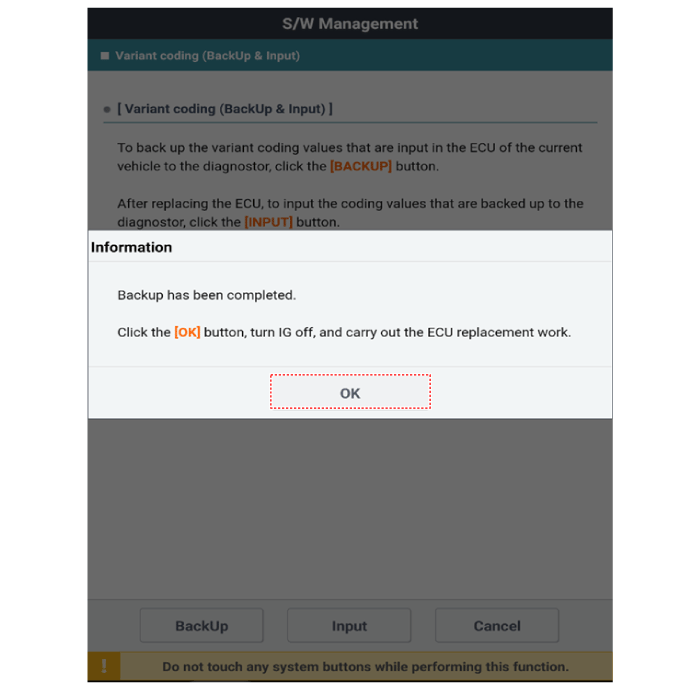
When the ‘Backup’ operation is completed, press the ‘OK’ button.
|
| 9. |
Replacement the new instrument cluster.
(Refer to Body Electrical System - "Instrument Cluster")
|
| 10. |
Connect the cable of diagnostic tool to the data link connector in driver
side crash pad lower panel.
|
| 11. |
Select the 'S/W Management' and 'Car model'.
|
| 12. |
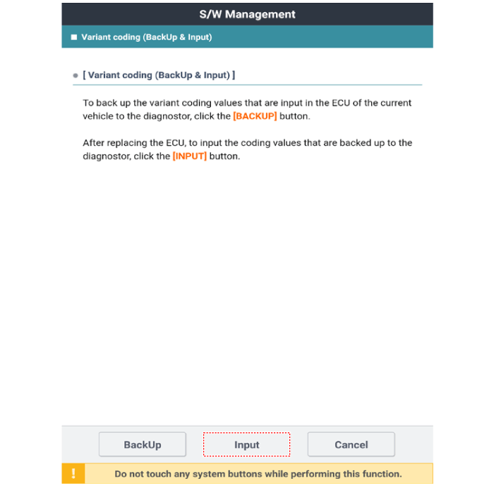
Select the 'Variant coding (Backup & Input).
|
| 13. |
After checking purpose and enable condition, press the ‘OK’ button.
|
| 14. |
Press the ‘OK’ button.
|
| 15. |
Select ‘Input’ to input the coding values.
|
| 16. |
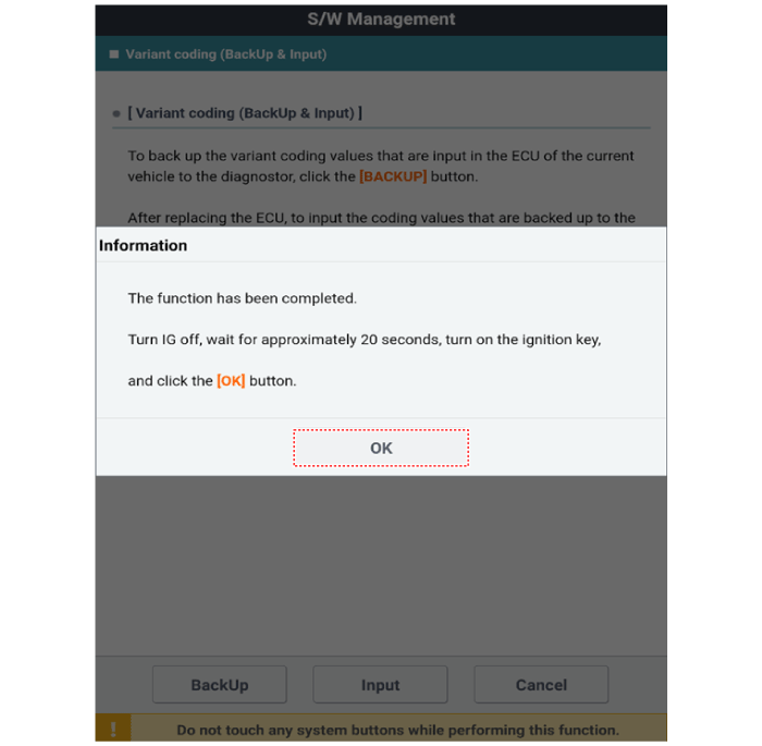
When the ‘Input’ operation is completed, press the ‘OK’ button.
|
 Fuses And Relays
Components and components location Component Location 1. Engine room relay box 2. Sub relay box 3. ICU Junction block 4. ICM relay box Relay Box (Engine Compartment). Components and components location ...
 Power Door Locks
Components and components location Component Location 1. Driver power window main switch 2. IBU (Integrated Body Control Unit) 3. Door lock switch 4. Tailgate lock actuator & switch 5. Front door lock ...
See also:
Smooth cornering
Avoid braking or gear changing in corners, especially when roads are wet. Ideally, corners should always be taken under gentle acceleration. If you follow these suggestions, tire wear will be held to ...
Rear Glass Defogger
Components and components location Component Location 1. Rear glass defogger relay (Buil-in engine room relay box) 2. Rear glass defogger switch (Dual type) 3. Rear glass defogger switch (Manual type) ...
Rear Seat Belt
Rear Seat Belt Retractor. Components and components location Component Location 1. Second Row Seat Belt Retractor 2. Third Row Seat Belt Retractor Rear Seat Belt Retractor. Repair procedures Replacement ...

