 Hyundai Santa Fe (TM): Power Door Locks
Components and components location
| Component Location |
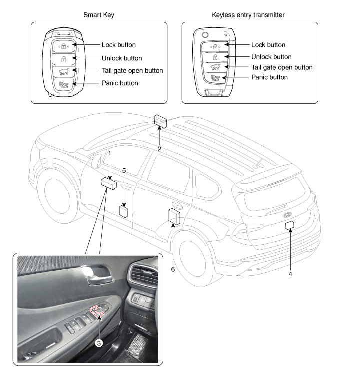
| 1. Driver power
window main switch 2. IBU (Integrated Body Control Unit) 3. Door lock switch |
4. Tailgate lock
actuator & switch 5. Front door lock actuator & switch 6. Rear door lock actuator & switch |
Power Door Lock Actuators. Repair procedures
| Inspection |
| 1. |
Remove the front door trim.
(Refer to Body - "Front Door Trim")
|
| 2. |
Remove the front door module.
(Refer to Body - "Front Door Module")
|
| 3. |
Disconnect the connectors from the actuator.
|
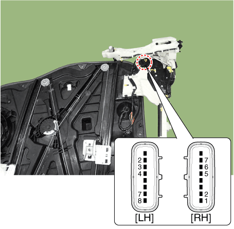
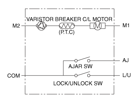
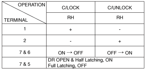
| 4. |
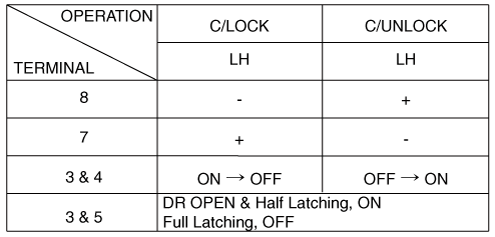
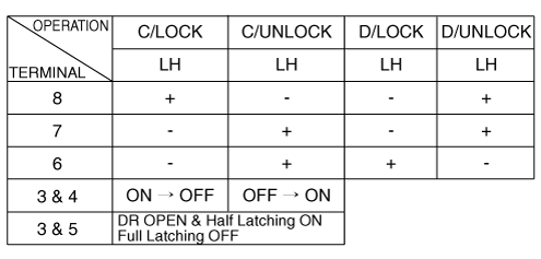
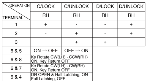
Check actuator operation by connecting power and ground according to
the table.
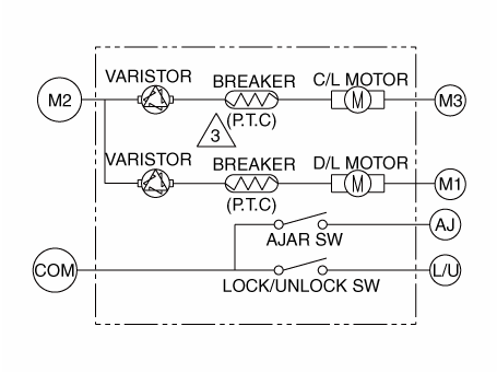
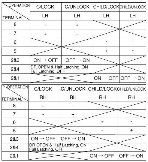
[Dead Lock]
[Central Lock]
[Central Lock]
[Dead Lock]
Driver
Passenger
|

| 1. |
Remove the rear door trim.
(Refer to Body - "Rear Door Trim")
|
| 2. |
Remove the rear door module.
(Refer to Body - "Rear Door Module")
|
| 3. |
Disconnect the connectors from the actuator.
|
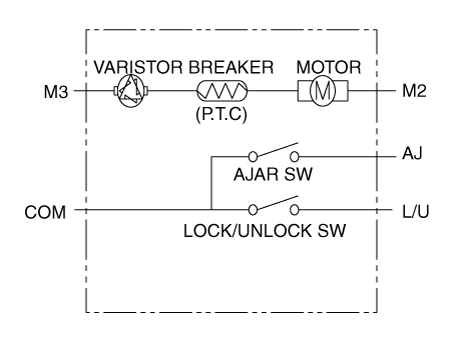
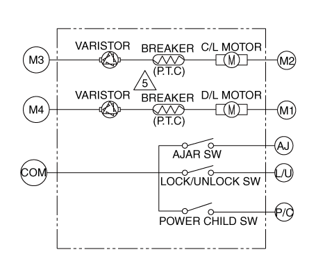
| 4. |
Check actuator operation by connecting power and ground according to
the table.
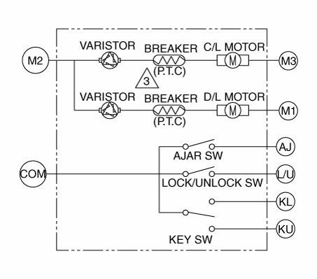
[Central Lock]
[Dead Lock]
[Child Lock]
|

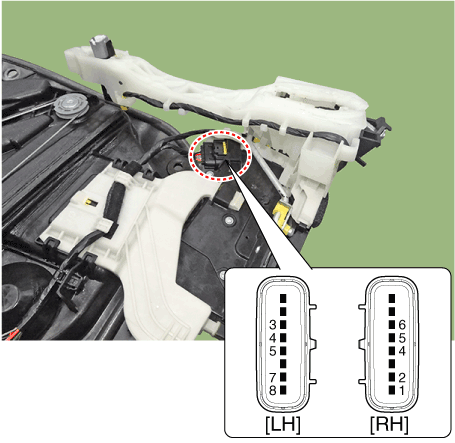
| 1. |
Remove the tailgate trim.
(Refer to Body - "Tailgate Trim")
|
| 2. |
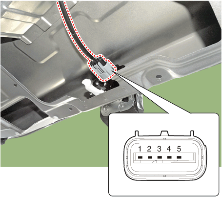
Disconnect the 4P connector from the actuator.
|
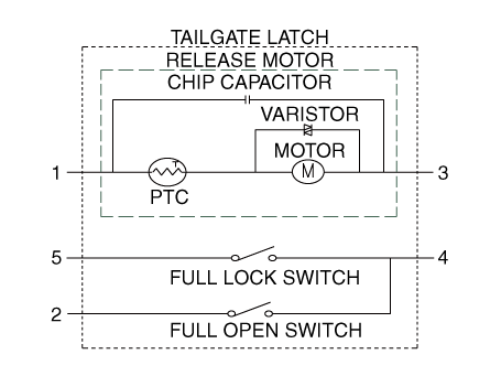
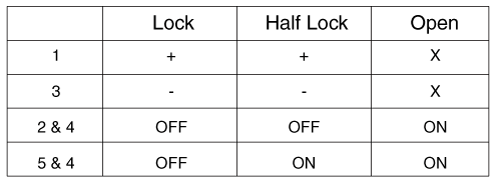
| 3. |
Check actuator operation by connecting power and ground according to
the table.
|
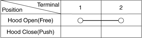
| 1. |
Disconnect the connector and bolts from the hood switch.
|
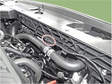
| 2. |
Check for continuity between the terminals and ground according to the
table.
|
Power Door Lock Switch. Repair procedures
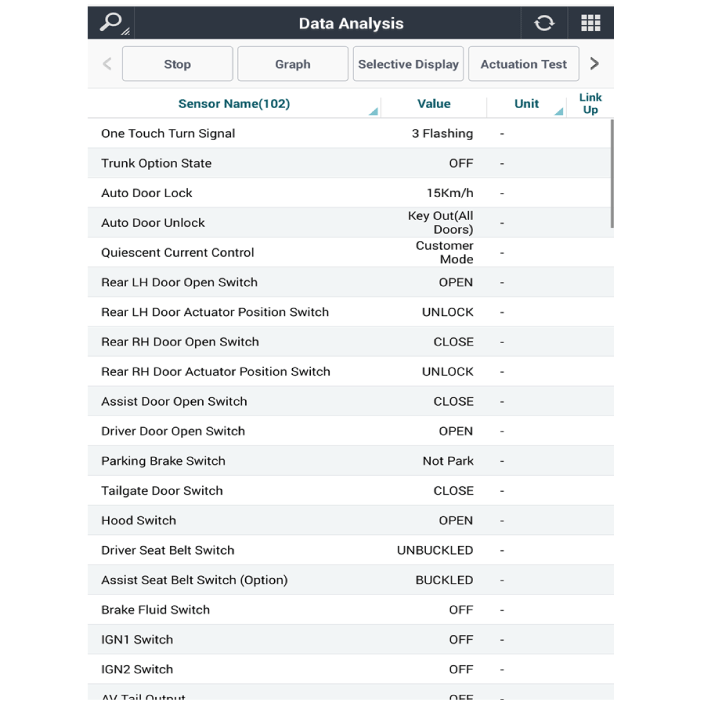
| Diagnosis with Diagnostic Tool |
| 1. |
In the body electrical system, failure can be quickly diagnosed by using
the vehicle diagnostic system.
The diagnostic system provides the following information.
|
| 2. |
If diagnose the vehicle by diagnostic tool, select "DTC Analysis" and
"Vehicle".
|
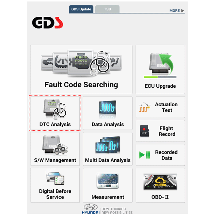
| 3. |
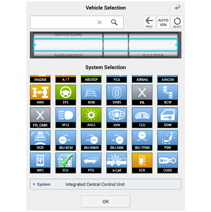
If check current status, select the "Data Analysis" and "Car model".
|

| 4. |
Select the 'ICU' to search the current state of the input/output data.
|
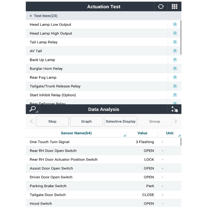
| 5. |
To forcibly actuate the input value of the module to be checked, select
option 'Actuation Test'.
|
| Removal |
| 1. |
Disconnect the negative (-) battery terminal.
|
| 2. |
Remove the front door trim.
(Refer to Body - "Front Door Trim")
|
| 3. |
Remove the power window bezzel assembl (A) after loosening the mounting
screws.
|
| 4. |
Remove the power window switch assembly (A) after loosening the mounting
screws.
|
| Installation |
| 1. |
Install the power window switch assembly.
|
| 2. |
Install the front door trim after connecting the connector.
|
 Indicators And Gauges
Troubleshooting Troubleshooting Symptom Possible cause Remedy Speedometer does not operate Cluster fuse (10A) blown Check for short and replace fuse Speedometer faulty Check speedometer CAN line faulty ...
 Power Door Mirrors
Components and components location Component Location 1. Power door mirror 2. Power door mirror switch 3. Power folding mirror switch Power Door Mirror Switch. Schematic diagrams Circuit Diagram Power ...
See also:
How does the air bag system operate
Air bags are activated (able to inflate if necessary) only when the ignition switch is turned to the ON or START position. The appropriate air bags inflate instantly in the event of serious frontal or ...
Heated Oxygen Sensor (HO2S). Description and Operation
Description Heated Oxygen Sensor (HO2S) consists of zirconium and alumina and is installed both upstream and downstream of the Manifold Catalytic Converter. The sensor output voltage varies in accordance ...
Fuel Tank Pressure Sensor (FTPS). Repair procedures
Inspection 1. Connect the GDS on the Data Link Connector (DLC). 2. Measure the output voltage of the FTPS. Specification: Refer to "Specification" Removal 1. Turn the ignition switch OFF and ...
