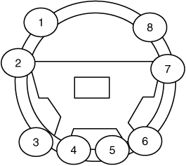
 Hyundai Santa Fe (TM): Steering wheel
Components and components location
| Components |
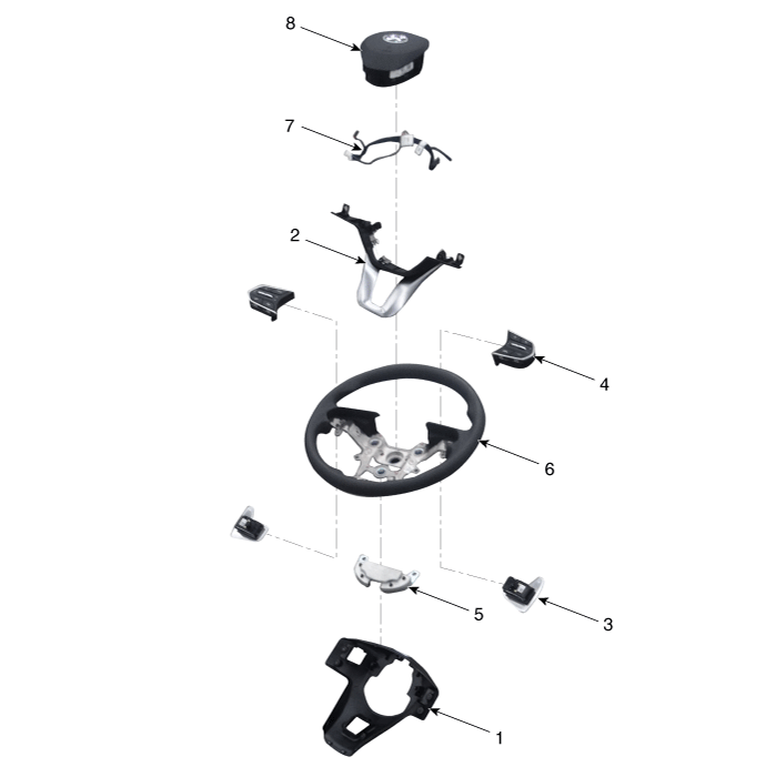
| 1. Lower cover 2. Switch bezel 3. Remote control switch 4. Paddle shift |
5. Damper 6. Steering Wheel 7. Wiring 8. Drive airbag module (DAB) |
Repair procedures
| Removal |
| 1. |
Turn the steering wheel so that the front wheels can face straight ahead.
|
| 2. |
Turn the ignition switch OFF and disconnect the battery negative (-)
cable.
|
| 3. |
Remove the drive airbag module.
(Refer to Restraint - "Drive Air Bag Module")
|
| 4. |
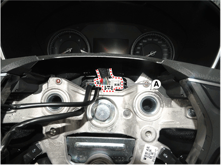
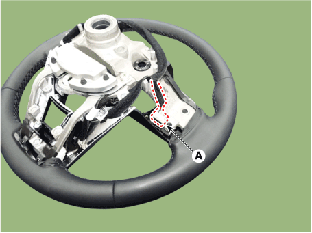
Disconnect the steering wheel connector (A).
|
| 5. |
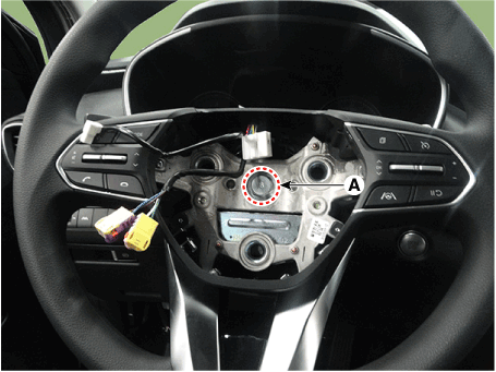
Remove the steering wheel after loosening the bolt (A).
|
| Disassembly |
[Non-Paddle Shift Type]
| 1. |
Loosen the screw and then remove the lower cover (A).
|
| 2. |
Disconnect the remote control switch connector (A).
|
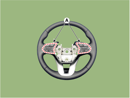
| 3. |
Loosen the screw and then remove the remote control switch (A).
|
| 4. |
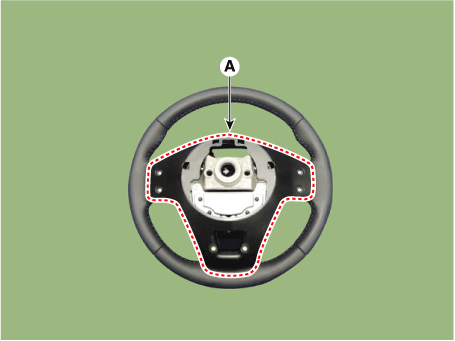
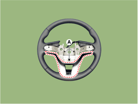
Remove the steering wheel bezel (A).
|
| 5. |
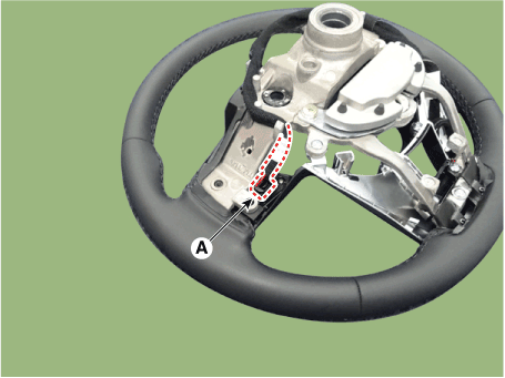
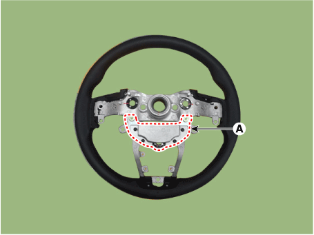
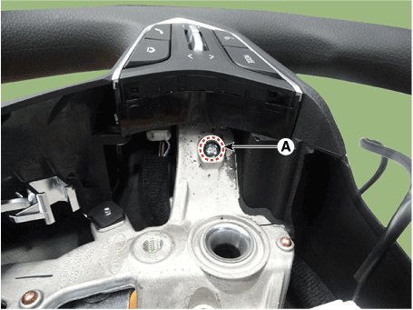
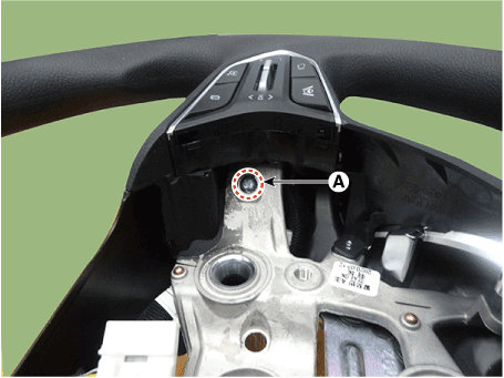
Remove the steering wheel damper (A) after loosening the mounting bolts.
|
[Paddle Shift Type]
| 1. |
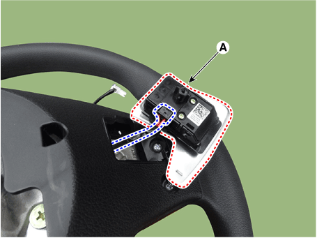
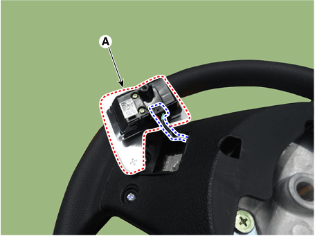
Loosen the paddle shift switch mounting screw (A).
|
| 2. |
Remove the paddle shift switch (A) after disconnecting the connector.
|
| 3. |
Remove the lower cover (A) after loosening the screw.
|
| 4. |
Disconnect the remote control switch connector (A).
|
| 5. |
Remove the remote control switch (A) after loosening the screw.
|
| 6. |
Remove the steering wheel bezel (A).
|
| 7. |
Remove the steering wheel damper (A) after loosening the mounting bolts.
|
| Reassembly |
| 1. |
To reassembly, reverse the disassembly procedure.
|
| Installation |
| 1. |
To install, reverse the removal procedures.
|
Heated Steering wheel. Description and operation
| Description |
Heated pads to grip the steering grip makes the fever.
Heated pad

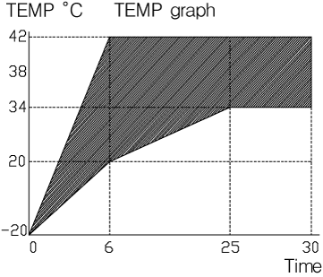
Heated Steering wheel. Specifications
| Specifications |
|
Item |
Specification |
|
Voltage |
13.5 V |
|
Heated pad resistance |
1.68 Ω ± 10 % |
|
NTC resistance |
10.0 kΩ ± 5 % (25 °C) |
Heated Steering wheel. Schematic diagrams
| System Circuit Diagram |
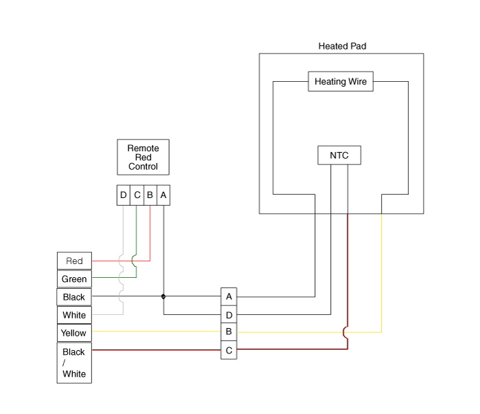

Terminal Function
|
Item |
Pin |
Function |
Wire color |
|
Pad |
A |
HEATER |
Red / Black |
|
B |
GND |
Brown / Black |
|
|
C |
NTC- |
Black |
|
|
D |
NTC+ |
Black |
|
|
Remote control |
A |
GND |
Black |
|
B |
BAT |
Red |
|
|
C |
LED |
Green |
|
|
D |
SWITCH |
White |
Heated Steering wheel. Repair procedures
| Inpection |
| 1. |
Measure a resistance of NTC and Heated pad.
|
| 2. |
Measure a temperature.
|
 Repair procedures
Service Adjustment Procedure Steering Wheel Play Inspection 1. Turn the steering wheel so that the front wheels can face straight ahead. 2. Mark the center of the steering wheel. 3. Measure the distance ...
 Motor Driven Power Steering
Description and operation Description MDPS (Motor Dirven Power Steering) system uses an electric motor to assist the steering force and it is an engine operation independent steering system. MDPS control ...
See also:
Owner maintenance
The following lists are vehicle checks and inspections that should be performed by the owner or an authorized HYUNDAI dealer at the frequencies indicated to help ensure safe, dependable operation of your ...
Front Seat Frame Assembly. Components and Components Location
Component Location 1. Front seat back frame assembly 2. Front seat cushion frame assembly ...
Components and components location
Components Location 1. Crankcase pressure regulating valve (PRV) 2. Canister 3. Purge control solenoid valve (PCSV) 4. Fuel tank air filter 5. Catalytic converter (WCC) 6. Catalytic converter (UCC) 1. ...

