 Hyundai Santa Fe (TM): Windshield Wiper/Washer
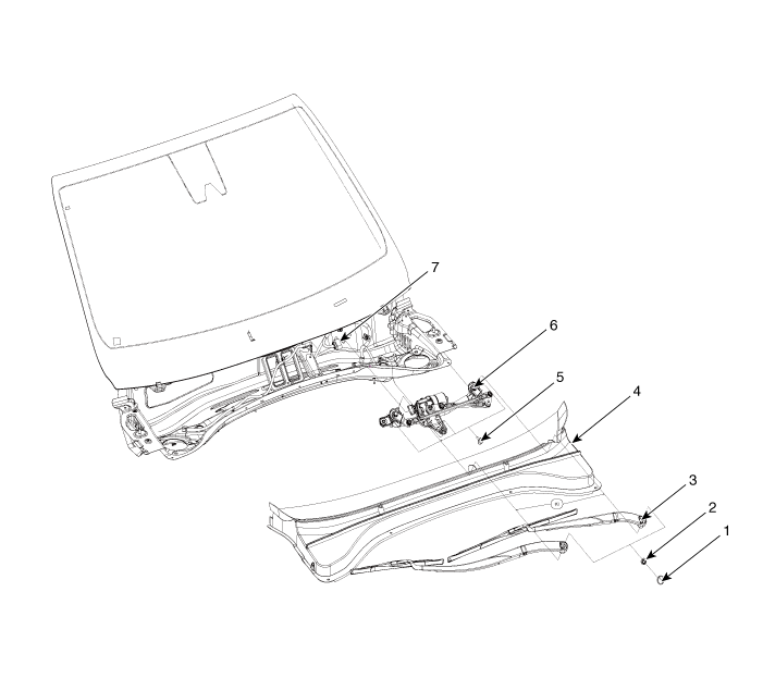
Components and components location
| Component Location |
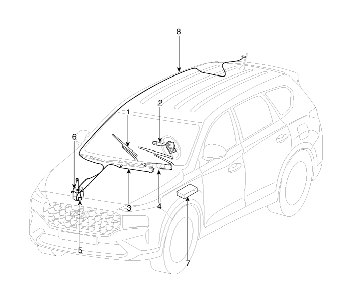
| 1. Windshield
wiper arm & blade 2. Wiper & washer switch 3. Windshield washer hose 4. Windshield wiper motor & linkage |
5. Washer motor 6. Washer reservoir 7. Front wiper relay (Engine room relay box) 8. Rear washer hose & nozzle |
Windshield Wiper-Washer Switch. Repair procedures
| Removal |
| 1. |
Disconnect the negative (-) battery terminal.
|
| 2. |
Remove the steering wheel.
(Refer to - "Steering Wheel")
|
| 3. |
Remove the steering columm shround.
(Refer to - "Steering Columm Shround panel")
|
| 4. |
Remove the clock spring.
(Refer to Restraint - "Driver Airbag(DAB) and Clock Spring")
|
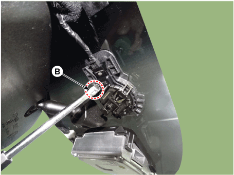
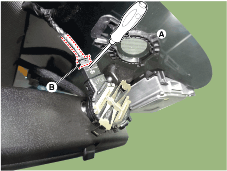
| 5. |
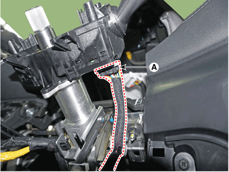
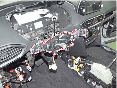
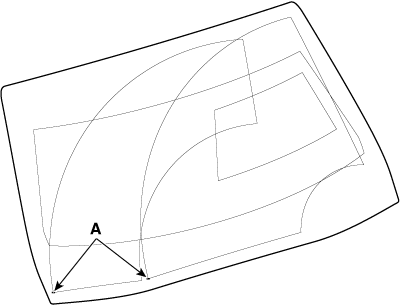
Remove the multifunction connector (A).
|
| 6. |
Remove the multifunction switch (A) after loosening the mounting screws
(2EA).
|
| Installation |
| 1. |
Install the multifunction switch after connecting the connector.
|
| 2. |
Install the clock spring and steering.
|
| 3. |
Install the upper and lower shroud.
|
| 4. |
Install the steering wheel.
|
| Inspection |
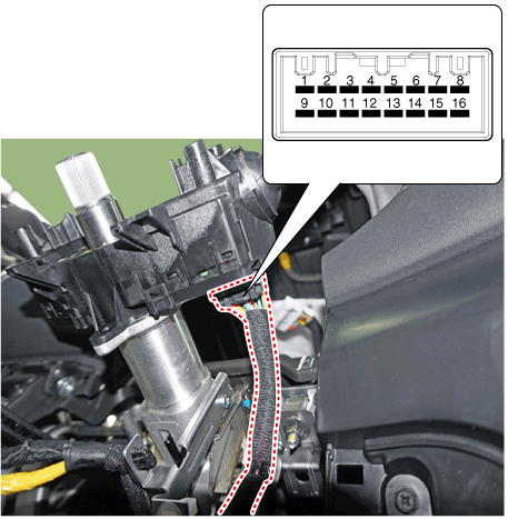
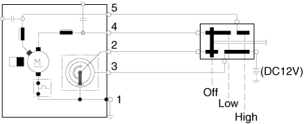
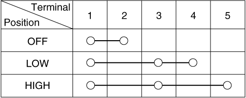
| 1. |
Check for continuity between the terminals in each switch position as
shown below.
|
Inspection (With diagnostic tool)
| 1. |
In the body electrical system, failure can be quickly diagnosed by using
the vehicle diagnostic system (diagnostic tool).
The diagnostic system (diagnostic tool) provides the following information.
|
| 2. |
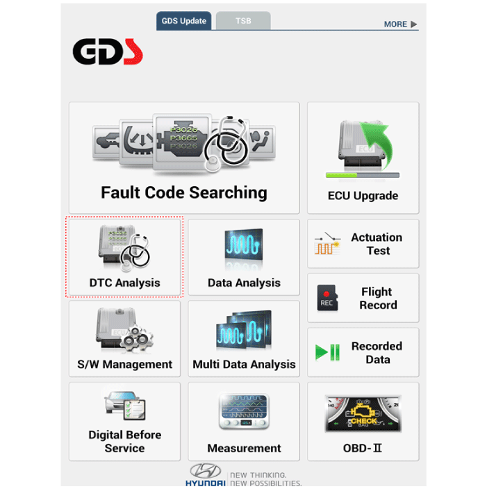
If diagnose the vehicle by diagnostic tool, select "DTC Analysis" and
"Vehicle".
|
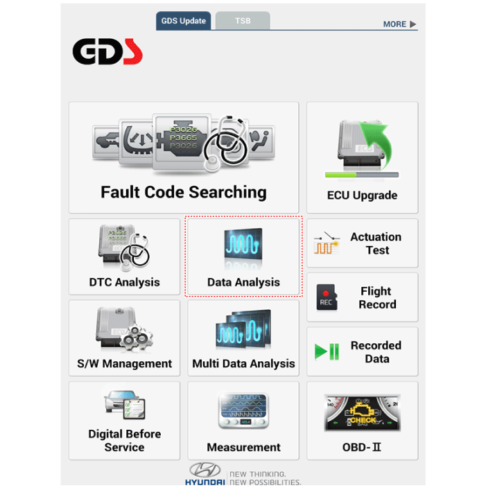
| 3. |
If check current status, select the "Data Analysis" .
|
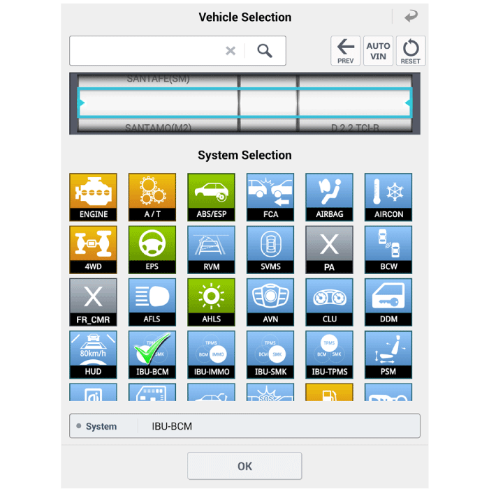
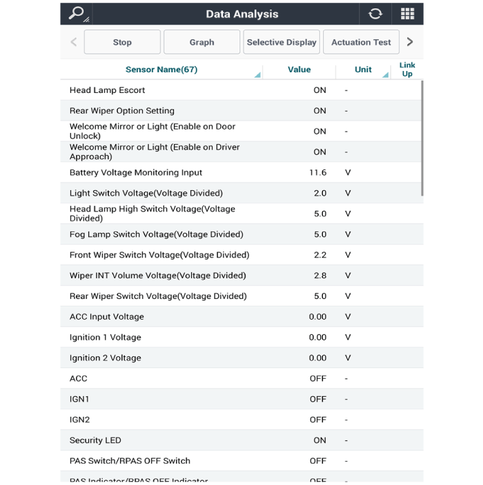
| 4. |
Select the 'IBU_BCM' to search the current state of the input/output
data.
|
Front Wiper Motor. Components and components location
| Component Location |
| 1. Cap 2. Nut 3. Wiper arm & blade 4. Cowl top cover |
5. Bolt 6. Wiper motor & linkage assembly 7. Wiper motor connector |
Front Wiper Motor. Repair procedures
| Removal |
| 1. |
Disconnect the negative (-) battery terminal.
|
| 2. |
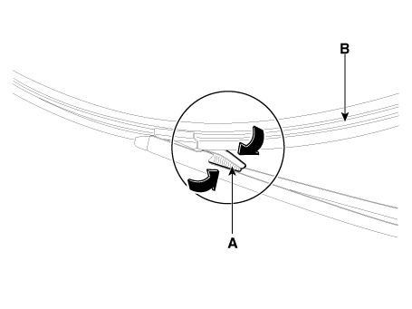
If necessary, release the wiper blade fixing clip(A) by pulling up and
remove the wiper blade(B) from the inside radius of wiper arm.
|
| 3. |
Remove the cowl top cover.
(Refer to Body - "Cowl Top Cover")
|
| 4. |
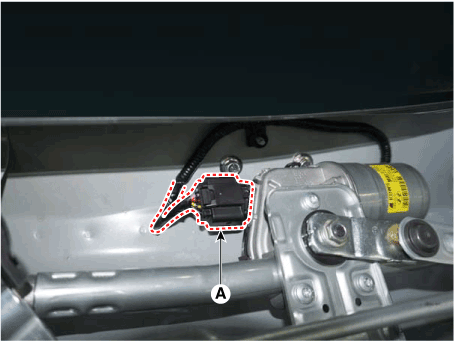
Disconnect the wiper motor connector (A) from the wiper motor & linkage
assembly.
|
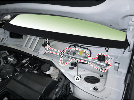
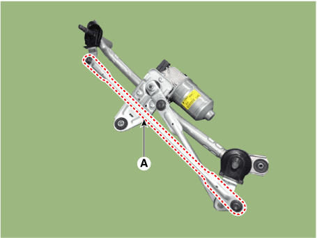
| 5. |
Remove the windshield wiper motor and linkage assembly (A) after removing
2 bolts.
|
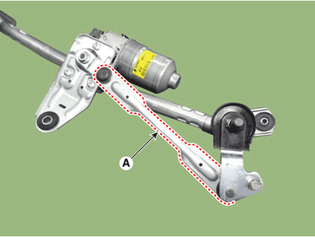
| 6. |
Hold the wiper motor crank arm and remove the upper linkage (A) from
the wiper motor crank arm.
|

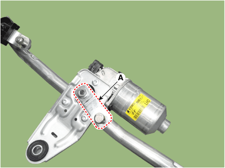
| 7. |
Remove the lower linkage (A) from the wiper motor crank arm.
|
| 8. |
Remove the crank arm (B) after loosening a nut (A).
|
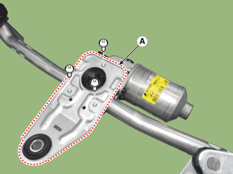
| 9. |
Remove the bracket (A) after loosening the screws (3EA).
|
| 10. |
Remove the wiper motor from the tube.
|
| Installation |
| 1. |
Install the wiper motor and linkage assembly and then connect the wiper
motor connector.
|
| 2. |
Install the cowl top cover.
|
| 3. |
Install the windshield wiper arm and blade.
|

| 4. |
Install the wiper arm and blade to the specified position.
A: Auto stop position (Blade)
|
| Inspection |
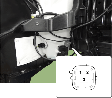
Speed Operation Check
| 1. |
Remove the connector (A) from the wiper motor.
|
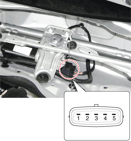
| 2. |
Attach the positive (+) lead from the battery to terminal 3 and the
negative (-) lead to terminal 1.
|
| 3. |
Check that the motor operates at low or high speed as below table.
|
Diagnosis with diagnostic tool
| 1. |
In the body electrical system, failure can be quickly diagnosed by using
the vehicle diagnostic system (diagnostic tool).
The diagnostic system (diagnostic tool) provides the following information.
|
| 2. |
If diagnose the vehicle by diagnostic tool, select "DTC Analysis" and
"Vehicle".
|
| 3. |
Select the 'Data Analysis'.
|
| 4. |
Select the 'IBU_BCM' to search the current state of the input/output
data.
|
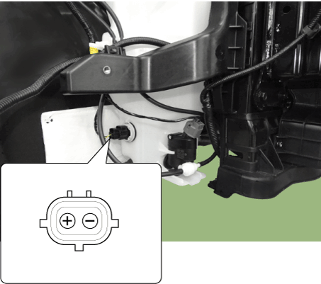
Front Washer Motor. Repair procedures
| Inspection |
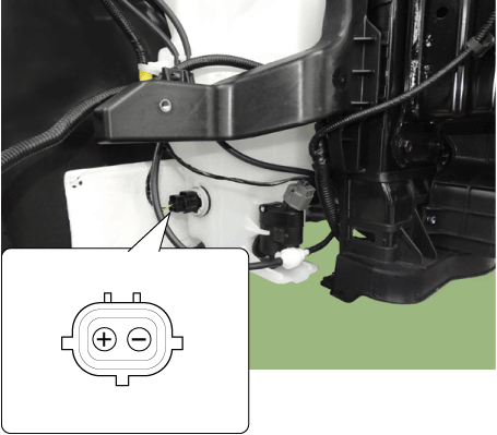
Front and Rear Washer Motor
| 1. |
With the washer motor connected to the reservoir tank, fill the reservoir
tank with water.
|
| 2. |
Connect positive (-) battery cables to terminal 1 and negative (+) battery
cables to terminal 2 respectively.
|
| 3. |
Check that the motor operates normally and the washer motor runs and
water sprays from the front nozzles.
|
| 4. |
If they are abnormal, replace the washer motor.
[Standard Type]
|
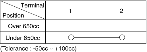
Washer Fluid Level Sensor Switch
| 1. |
Disconnect the negative(-) battery terminal.
|
| 2. |
Drain the washer fluid less than 650 cc.
|
| 3. |
Check for continuity between the No. 1 and No.2 terminal in each float
position.
There should be continuity when the float is down.
There should be no continuity when the float is up.
|
| 4. |
If the continuity is not as specified, replace the washer fluid level
switch
|
| Removal |
|
| 1. |
Disconnect the negative (-) battery terminal.
|
| 2. |
Remove the front bumper cover.
(Refer to Body - "Front Bumper Cover")
|
| 3. |
Remove the washer hose and disconnect the washer motor connector and
washer fluid level sensor connector.
|
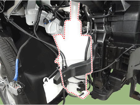
| 4. |
Remove the washer motor.
|
| 5. |
Remove the washer reservoir (A) after loosening bolts .
|
| Installation |
| 1. |
Reassemble the washer reservoir.
|
| 2. |
Install the head lamp washer pump and washer motor.
|
| 3. |
Install the washer nozzle.
|
| 4. |
Connect the washer motor connector and washer hose.
|
| 5. |
Reassemble the front bumper cover.
|
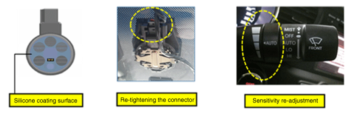
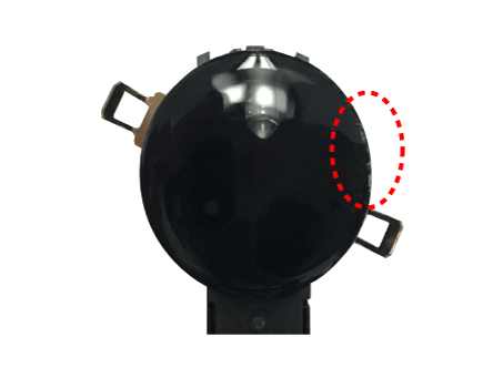
Rain Sensor. Description and operation
| Description |
Integrated Rain Sensor
Integrated rain sensor (A) controls three systems: front wiper, auto-light,
and central air conditioner.
| 1. |
Wiper Control System
When "AUTO" switch signal is received from the multi-function switch
on the right, the integrated rain sensor detects the amount of rainfall.
The sensor is installed inside the upper part of the front window for
wiper motor control.
This system automatically controls the operation duration and speed
of the wiper depending on the measured amount of rainfall even if the
driver does not operate the wiper switch.
|
| Functions and Operating Principles |
Basic Principle
| 1. |
Detecting the amount of rainfall
The light (beam) emitted from light emitting diodes (LED) is totally
reflected on the external surface of the windshield and comes back to
the photo diodes. When there is water on the external surface of the
windshield, the light is optically separated and reflected partially
and the remaining brightness is measured by the photo diodes. Water
remaining on the windshield results in the light being not totally reflected.
The loss of brightness due to this indicates how much the glass surface
is wet.
|
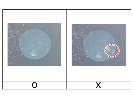
Interference
Rain sensor might malfunction due to the interferences listed below.
| 1. |
Dust on the measuring surface and other surfaces on the light path (surface
of light emitting diodes and photo diodes, fiber optics, bracket, and
glass surface of windshield joint area) weakens the received light.
|
| 2. |
Movement of windshield and bracket
|
| 3. |
Movement of bracket due to vibration
|
| 4. |
Damaged wiper blade
|
|
Automatic Operation
| 1. |
Operational status of rain sensor
|
Safety Function
| 1. |
When there is ice or foreign matter in the detecting area, integrated
rain sensor cannot recognize the condition for operation correctly.
|
Detecting Special Conditions
| 1. |
Rain sensor
|
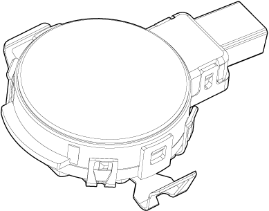
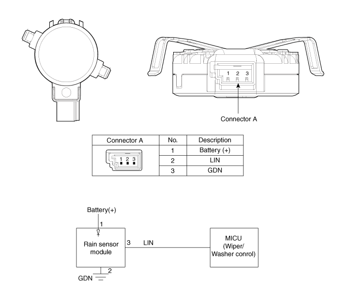
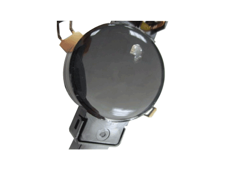
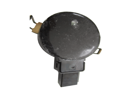
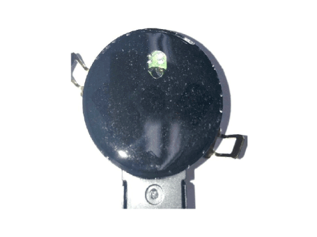
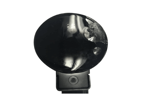
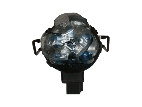
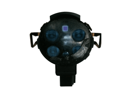
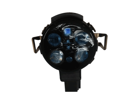
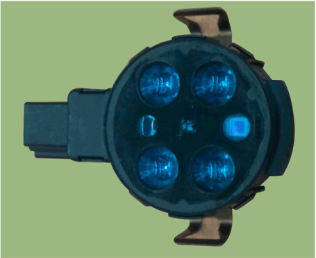
Rain Sensor. Components and components location
| Components |
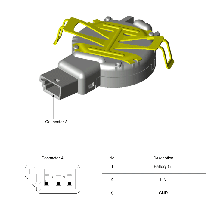
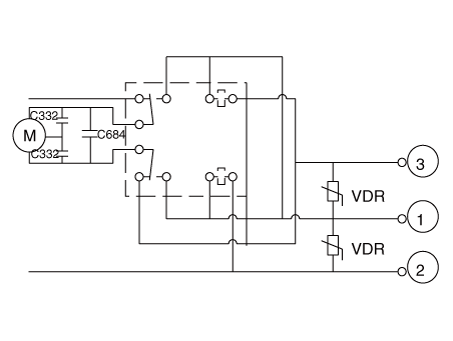
Rain Sensor. Schematic diagrams
| Circuit Diagram |
Rain Sensor. Repair procedures
| Removal |
|
|

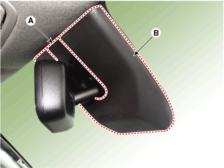
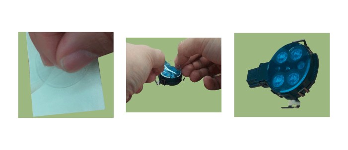
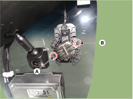
| 1. |
Remove the rain sensor cover (A)&(B).
|
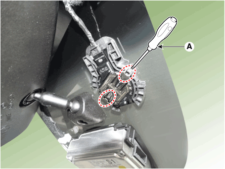
| 2. |
To remove the latch, pull aside the latch using the cover hole with
a small flat-blade screwdriver (A).
|
| 3. |
Remove the rain sensor.
|
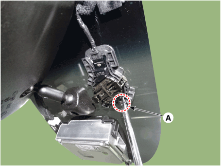
| 4. |
Disconnect the wiring harness connector (B) from the rain sensor by
inserting a small flat-blade screwdriver (A) into the space.
|
| Installation |
|
|||||||||||||||||||||||||||||||||||||||||||||||||||||||
| 1. |
Connect the rain sensor connector.
|
| 2. |
Push one of the latch of spring arm (A) down until it snaps and you
hear a click sound.
And then push the latch of second spring arm (B) for keeping the sensor
in right position.
|
 Power Tailgate Module
Description and operation Description Power tailgate is an electro-mechanical system designed to provide power opening and closing of the tailgate through the push of a button of a remote key (fob), console ...
 Rear Wiper/Washer
Components and components location Component Location 1. Rear wiper arm nut 2. Rear wiper arm & blade 3. Rear wiper grommet 4. Rear wiper motor assembly Rear Wiper Motor. Repair procedures Inspection ...
See also:
Additional safety precautions
Never let passengers ride in the cargo area or on top of a foldeddown back seat. All occupants should sit upright, fully back in their seats with their seat belts on and their feet on the floor. Passengers ...
Variable Intake Solenoid (VIS) Valve. Schematic Diagrams
Circuit Diagram ...
Glove box
Type A Type B The glove box can be locked and unlocked with the mechanical key (1). To open the glove box, push the button (2) and the glove box will automatically open (3). Close the glove box after ...
