 Hyundai Santa Fe (TM): Auto Lighting Control System
Description and operation
| Description |
It's a system that uses illumination sensor to automatically turn ON the tail
lamp and head lamp based on the change in surrounding environment's illumination
condition. It activates when the vehicle enters/exits tunnel, or when the illumination
condition in surrounding environment changes due to rain, snow, or fog. Precautions
corresponding to the use of this system are as follows.
| 1. |
Do not add another device on top of this device.
|
| 2. |
Be sure to switch to manual during poor visibility climate, such as
fog, heavy rain, or cloudy weather.
|
| 3. |
Illumination intensity in an actual vehicle is not always constant,
and lamp ON/OFF time may very depending on the climate, season, and
surrounding environment.
|
| 4. |
Use this system only during sunrise and sunset period, and manually
control lamp ON/OFF for general conditions.
|
| 5. |
Error may occur if light block coating that may change interior illumination
is applied.
|
Components and components location
| Component Location |
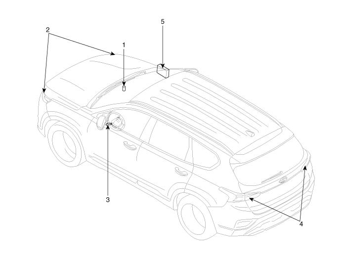
| 1. Auto light
sensor 2. Head lamps 3. Lighting switch (Auto) |
4. Tail lamps 5. IBU (Integrated Body Control Unit) |
Specifications
| Specifications |
|
Items |
Specifications |
|
|
Rated voltage |
5V |
|
|
Load |
Max. 1mA (When head lamp lighting) |
|
|
Illuminations (LUX) |
50 |
1.22 ± 0.27V |
|
150 |
3.23 ± 0.71V |
|
Schematic diagrams
| Circuit Diagram |
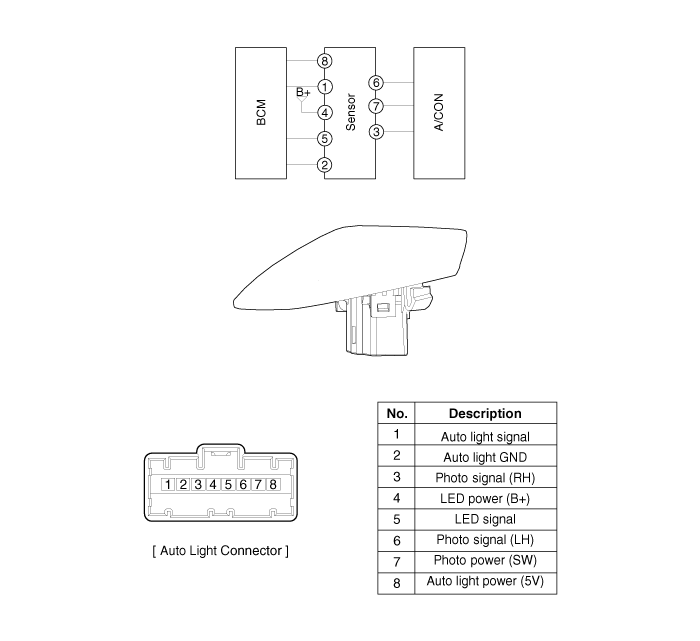
Auto Light Sensor. Repair procedures
| Inspection |
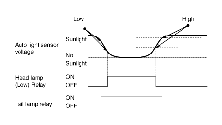
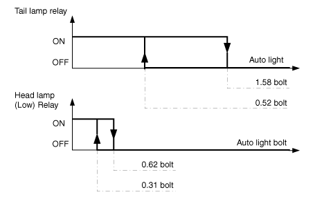
Check if the auto light control operates like a timing chart shown below. Tail
lamp output and head lamp (Low) output is controlled based on the auto light
sensor's input (illumination intensity) when the Auto Light Switch in Multi-Function
Switch is turned ON, and the vehicle is in IGN1 or IGN2 ON Mode. If IGN1 = ON,
BCM detects this voltage, and if the voltage exceeds rated voltage, then auto
light failure occurs. (below 4V or above 6V)
|
In the state of IGN1 ON, when multi function switch module detects auto light
switch on, tail lamp relay output and head lamp low relay output are controlled
according to auto light sensor's input.The auto light control doesn't work if
the pin sunlight supply (5V regulated power from Ignition 1 power to sunlight
sensor) is in short circuit with the ground.If IGN1 ON, The BCM monitors the
range of this supply and raises up a failure as soon as the supply’s voltage
is out of range. Then this failure occurs and as long as this is present, the
head lamp must be turned on without taking care about the sunlight level provided
by the sensor.This is designed to prevent any head lamp cut off when the failure
occurs during the night.
| Removal |
| 1. |
Disconnect the negative (-) battery terminal.
|
| 2. |
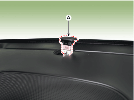
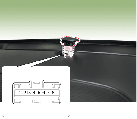
Remove the photo & auto light sensor (A) from crash pad upper side by
using a flat-tip screwdriver.
|
| 3. |
Remove the auto light connector.
|
| Installation |
| 1. |
Reconnect the auto light connector.
|
| 2. |
Install the auto light sensor.
|
 Lighting System
Components and components location Component Location 1. Head lamp (Low) 2. Head lamp (High) 3. Daytime running light (DRL)/Positioning lamp 4. Turn signal lamp 5. Head lamp (ADD Low) 6. Side repeater ...
 Auto Head Lamp Leveling Device
Components and components location Component Location 1. Head lamp leveling actuator Head Lamp Leveling Switch. Schematic diagrams Circuit diagram Head Lamp Leveling Switch. Repair procedures Inspection ...
See also:
Propeller Shaft Assembly
Components and components location Components 1. Front propeller shaft 2. Center bearing bracket 3. Rear propeller shaft Repair procedures Removal • Be careful not to damage the parts located ...
Ladder Frame. Repair procedures
Removal • Use fender covers to avoid damaging painted surfaces. • To avoid damage, unplug the wiring connectors carefully while holding the connector portion. • Mark all wiring and hoses to avoid ...
Side curtain
To use the side curtain: 1. Lift the curtain by the hook (1). 2. Hang the curtain on both sides of the hook. ...


