 Hyundai Santa Fe (TM): Body Side Molding
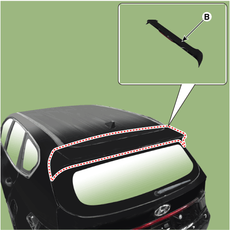
Rear Spoiler. Components and components location
| Component Location |
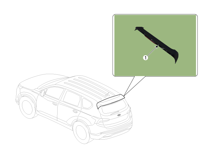
| 1. Rear Spoiler |
Rear Spoiler. Repair procedures
| Replacement |
|
|
| 1. |
Remove the tailgate upper trim.
(Refer to Tailgate - "Liftgate Trim")
|
| 2. |
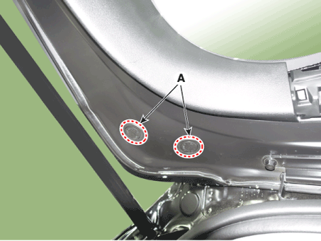
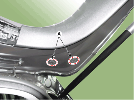
Remove the rear spoiler plug hole (A).
[LH]
[RH]
|
| 3. |
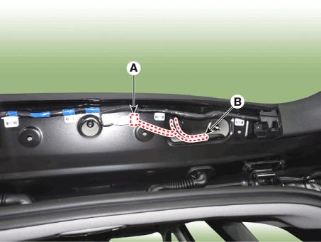
Separate the rear stop lamp connector (A) and rear washer nozzle (B).
|
| 4. |
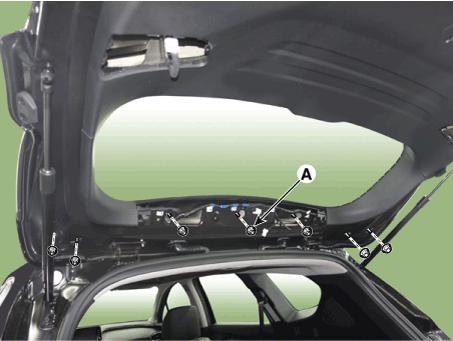
Loosen the mounting nuts (A) and remove the rear spoiler (B).
|
| 5. |
To install, reverse the removal procedure.
|
Fender Garnish. Repair procedures
| Replacement |
|
|
| 1. |
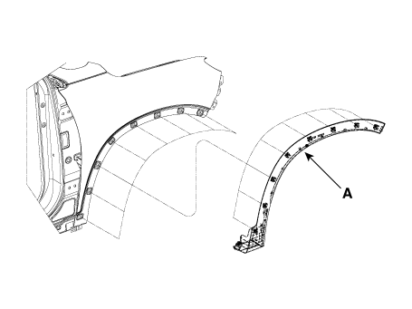
Using a screwdriver or remover, remove the fender garnish (A).
|
| 2. |
To install, reverse removal procedure.
|
Quarter Garnish. Repair procedures
| Replacement |
|
|
| 1. |
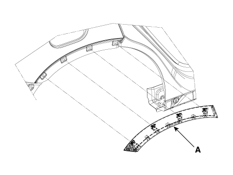
Using a screwdriver or remover, remove the quarter garnish (A).
|
| 2. |
To install, reverse removal procedure.
|
Side Sill Molding. Repair procedures
| Replacement |
|
|
| 1. |
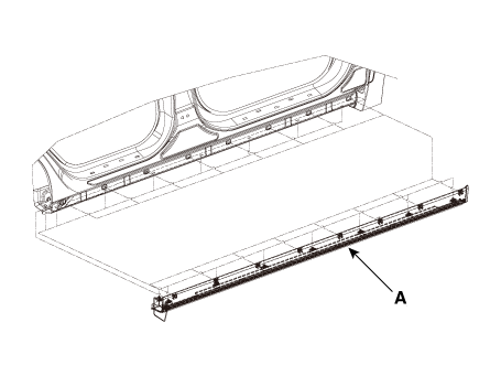
Using a remover, remove the side sill molding (A).
|
| 2. |
To install, reverse removal procedure.
|
Roof Side Molding. Repair procedures
| Replacement |
|
|
| 1. |
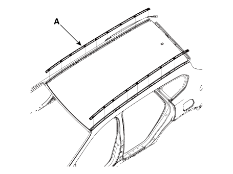
Using a screwdriver or remover, remove the roof side molding (A).
|
| 2. |
To install, reverse removal procedure.
|
Roof Rack. Components and components location
| Components Location |
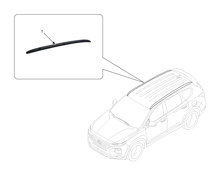
| 1. Roof rack
assembly |
Roof Rack. Repair procedures
| Removal |
|
| 1. |
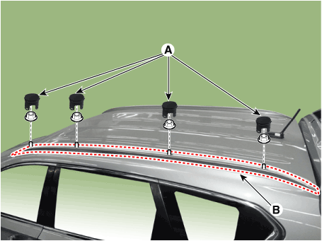
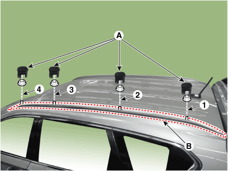
Remove the roof rack side cap (A).
|
| 2. |
Loosen the nuts and remove the roof rack assembly (B).
|
| Installation |
| 1. |
Install the roof rack assembly (B).
|
| 2. |
Install the roof rack side cap (A).
|
Front Wheel Guard. Repair procedures
| Replacement |
|
| 1. |
Remove the front tire.
|
| 2. |
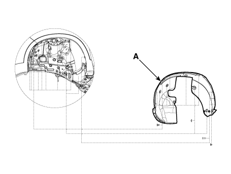
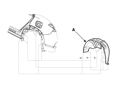
Loosen the mounting clip,nuts and screws , and remove the front wheel
guard (A).
|
| 3. |
To install, reverse the removal procedure.
|
Rear Wheel Guard. Repair procedures
| Replacement |
|
| 1. |
Remove the rear tire.
|
| 2. |
Loosen the mounting clip and remove the rear wheel guard (A).
|
| 3. |
To install, reverse the removal procedure.
|
Door Garnish. Repair procedures
| Replacement |
|
| 1. |
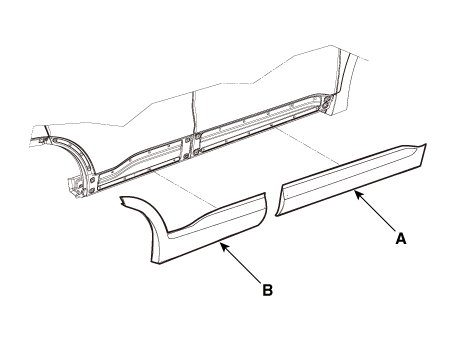
Using a remover or screwdriver and remove the front door garnish (A)
and rear door garnish (B).
|
| 2. |
To install, reverse the removal procedure.
|
 Rear Door
Components and components location Components 1. Rear door window glass 2. Rear door window glass run assembly 3. Rear door outside handle 4. Rear door outside handle pad 5. Rear door channel 6. Rear door ...
 Panorama Sunroof
Components and components location Component 1. Mechanism rail assembly 2. Center cover assembly 3. Roller blind motor 4. Glass motor 5. Panorama sunroof panel 6. Side molding 7. Decoration inner cover ...
See also:
CVVT (Continuously Variable Valve Timing) System. Description and Operation
Description Continuous Variable Valve Timing (CVVT) system advances or retards the valve timing of the intake and exhaust valve in accordance with the ECM control signal which is calculated by the engine ...
Blade inspection
✽ NOTICE Commercial hot waxes applied by automatic car washes have been known to make the windshield difficult to clean. Contamination of either the windshield or the wiper blades with foreign ...
IMS (Integrated Memory)
Description and operation Description The optimal seat position set by the driver is memorized into the power seat unit by using IMS switch. In case of the position change, the seat can restore its preset ...


